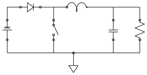
This example demonstrates an interesting use of decorations. A set of custom decorations have been defined to draw various electrical circuit elements. The code for the decorations can be found in the electComp.sty file.
To compile the example you will need the following style file:

Edit and compile if you like:
% Electrical circuits using decorations
% Author: B. Umesh Rai
\documentclass{article}%

\usepackage{electComp}
\usetikzlibrary{decorations,decorations.pathmorphing,decorations.pathreplacing}


\begin{document}
\title{Electrical Circuits with pgf}

\date{}
\maketitle
%-------------------------------------------

\begin{tikzpicture}[line width=1pt]
    \draw (0,0) -- ++(0,1cm);
    \draw[decorate, decoration=cell] (0,1cm) -- ++(0,1.5cm);
    \draw (0,2.5cm) |- ++(1cm,1cm);
    \draw[decorate, decoration=diode] (1cm,3.5cm) -- ++(1.5cm,0);
    \draw (2.5cm,3.5cm) -- ++(2,0);
    \draw (3.5cm,3.5cm) -- ++(0,-1);
    \draw[decorate, decoration=switch] (3.5cm,2.5cm) -- ++(0,-1.5cm);
    \draw[decorate,
        decoration={inductor,amplitude=0.35cm, segment length=0.75cm}]
        (4.5cm,3.5cm) -- ++(1.5cm,0);
    \draw (6cm,3.5cm) -- ++(1,0);
    \draw (7cm,3.5cm) -- ++(3,0);
    \draw (8cm,3.5cm) -- ++(0,-1);
    \draw[decorate, decoration=capacitor] (8cm,2.5cm) -- ++(0,-1.5cm);
    \draw (0cm,0cm) -| ++(8cm,1cm);
    \draw (3.5cm,0cm) -- ++(0cm,1cm);
    \draw (10cm,3.5cm) -- ++(0,-1);
    \draw[decorate, decoration=resistor] (10cm,2.5cm) -- ++(0,-1.5cm);
    \draw (8cm,0cm) -| ++(2cm,1cm);
    \draw[decorate, decoration=ground] (5,0cm) -- ++(0,-1.5cm);
\end{tikzpicture}

\end{document}
Click to download: circuit-decorations.tex • circuit-decorations.pdf
Open in Overleaf: circuit-decorations.tex

