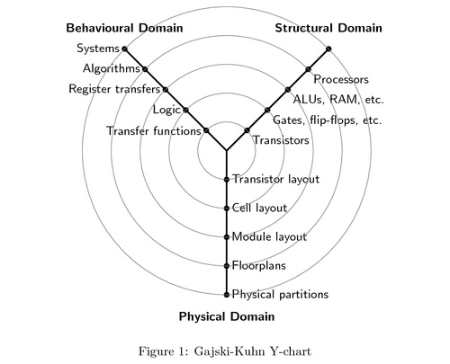
The Gajski-Kuhn Y-chart is a model which captures the considerations in designing semiconductor devices. The three domains of the Gajski-Kuhn Y-chart are on radial axes. Each of the domains can be divided into levels of abstraction, using concentric rings. At the top level (outer ring), we consider the architecture of the chip; at the lower levels (inner rings), we successively refine the design into finer detailed implementation:
Creating a structural description from a behavioural one is achieved through the processes of high-level synthesis or logical synthesis.
Creating a physical description from a structural one is achieved through layout synthesis.

Edit and compile if you like:
%% Copyright 2009 Ivan Griffin
%
% This work may be distributed and/or modified under the
% conditions of the LaTeX Project Public License, either version 1.3
% of this license or (at your option) any later version.
% The latest version of this license is in
%   http://www.latex-project.org/lppl.txt
% and version 1.3 or later is part of all distributions of LaTeX
% version 2005/12/01 or later.
%
% This work has the LPPL maintenance status `maintained'.
%
% The Current Maintainer of this work is Ivan Griffin
%
% This work consists of the files y_chart_common.tex and y_chart_example.tex

%Description
%-----------
%y_chart_common.tex -  TikZ code to draw the 3 axes of the
%                      Gajski-Kuhn Y-chart
%y_chart_example.tex - an example file which connects and describes
%                      the Y-chart

%Created 2009-11-20 by Ivan Griffin.  Last updated: 2009-11-20
%-------------------------------------------------------------


\documentclass{article}

\usepackage{tikz}
\usepackage[floats,active,tightpage]{preview}
\setlength\PreviewBorder{5pt}%


\usetikzlibrary{backgrounds,shapes,arrows,positioning,calc,snakes,fit}
\usepgflibrary{decorations.markings}

\begin{document}

\begin{figure}[htpb]
  \centering
  \begin{tikzpicture}[>=stealth',join=bevel,font=\sffamily,auto,on grid,decoration={markings,
    mark=at position .5 with \arrow{>}}]
    %\input{y_chart_common}
    \coordinate (behaviouralNode) at (135:4cm);
    \coordinate (structuralNode) at (45:4cm);
    \coordinate (physicalNode) at (270:4cm);
    \coordinate (originNode) at (0:0cm);

    \node [above=1em] at (behaviouralNode) {\textbf{Behavioural Domain}};
    \node [above=1em] at (structuralNode) {\textbf{Structural Domain}};
    \node [below=1em] at (physicalNode) {\textbf{Physical Domain}};

    \draw[-, very thick] (behaviouralNode.south) -- (0,0) node[left,pos=0]{Systems} node[left,pos=0.2]{Algorithms} node[left,pos=0.4]{Register transfers} node[left,pos=0.6]{Logic} node[left,pos=0.8]{Transfer functions};

    \draw[-, very thick] (structuralNode.south) -- (0,0) node[pos=0]{ } node[pos=0.2]{Processors} node[pos=0.4]{ALUs, RAM, etc.} node[pos=0.6]{Gates, flip-flops, etc.} node[pos=0.8]{Transistors};

    \draw[-, very thick] (physicalNode.south) -- (0,0) node[right,pos=0]{Physical partitions} node[right,pos=0.2]{Floorplans} node[right,pos=0.4]{Module layout} node[right,pos=0.6]{Cell layout} node[right,pos=0.8]{Transistor layout};

    \draw[fill] (barycentric cs:behaviouralNode=1.0,originNode=0) circle (2pt);
    \draw[fill] (barycentric cs:behaviouralNode=0.8,originNode=0.2) circle (2pt);
    \draw[fill] (barycentric cs:behaviouralNode=0.6,originNode=0.4) circle (2pt);
    \draw[fill] (barycentric cs:behaviouralNode=0.4,originNode=0.6) circle (2pt);
    \draw[fill] (barycentric cs:behaviouralNode=0.2,originNode=0.8) circle (2pt);

    \draw[fill] (barycentric cs:structuralNode=1.0,originNode=0) circle (2pt);
    \draw[fill] (barycentric cs:structuralNode=0.8,originNode=0.2) circle (2pt);
    \draw[fill] (barycentric cs:structuralNode=0.6,originNode=0.4) circle (2pt);
    \draw[fill] (barycentric cs:structuralNode=0.4,originNode=0.6) circle (2pt);
    \draw[fill] (barycentric cs:structuralNode=0.2,originNode=0.8) circle (2pt);

    \draw[fill] (barycentric cs:physicalNode=1.0,originNode=0) circle (2pt);
    \draw[fill] (barycentric cs:physicalNode=0.8,originNode=0.2) circle (2pt);
    \draw[fill] (barycentric cs:physicalNode=0.6,originNode=0.4) circle (2pt);
    \draw[fill] (barycentric cs:physicalNode=0.4,originNode=0.6) circle (2pt);
    \draw[fill] (barycentric cs:physicalNode=0.2,originNode=0.8) circle (2pt);

    \draw[black!50] (0,0) circle (4.0cm);
    \draw[black!50] (0,0) circle (3.2cm);
    \draw[black!50] (0,0) circle (2.4cm);
    \draw[black!50] (0,0) circle (1.6cm);
    \draw[black!50] (0,0) circle (0.8cm);

  \end{tikzpicture}
  \caption{Gajski-Kuhn \index{Gajski-Kuhn Y-chart}Y-chart}
  \label{figure:gajski_kuhn_y_chart__levels_of_abstraction}
\end{figure}

The three domains of the Gajski-Kuhn Y-chart are on radial axes.  Each of the domains can be divided into levels of abstraction, using concentric rings.  At the top level (outer ring), we consider the architecture of the chip; at the lower levels (inner rings), we successively refine the design into finer detailed implementation:

Creating a structural description from a behavioural one is achieved through the processes of high-level synthesis or logical synthesis.

Creating a physical description from a structural one is achieved through layout synthesis.

\end{document}
Click to download: gajski-kuhn-y-chart.tex • gajski-kuhn-y-chart.pdf
Open in Overleaf: gajski-kuhn-y-chart.tex

