


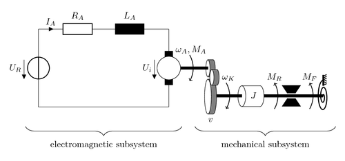
Model of a throttle valve that is used inside an internal combustion engine. The mechatronic system is modelled by simplified subsystems that allow an easier description. Was used in a student project at technical university Berlin.
Author: Mathias Busse, Germany (busse@teco.edu)
Edit and compile if you like:
% Model of a throttle valve that is used inside an internal
% combustion engine. The mechatronic system is modelled
% by simplified subsystems that allow an easier description.
% Was used in a student project at technical university Berlin
%
% Author: Mathias Busse, Germany (busse@teco.edu)
\documentclass{article}
\usepackage{tikz}
\usepackage[active,tightpage]{preview}
\PreviewEnvironment{tikzpicture}
\setlength\PreviewBorder{10pt}%
\usepackage[european]{circuitikz}
\usetikzlibrary{decorations.pathreplacing}
\begin{document}

\begin{circuitikz}
%	\draw [help lines] (-1,-2) grid (12,5);

	% electrical equivalent circuit
	\draw (0,3) to[V, v_=$U_R$] (0,0);
	\draw (0,3) to[R, i>^=$I_A$, l=$R_A$] (3,3);
	\draw (3,3) to[L, l=$L_A$] (4,3);

	\draw (4,3) -- (5,3);
	\draw (5,3) to[V, v_=$U_i$] (5,0);
	\draw (0,0) -- (5,0);

	% drive
	\draw[fill=black] (4.85,0.85) rectangle (5.15,2.15);
	\draw[fill=white] (5,1.5) ellipse (.45 and .45);

	% transmission gear one
	\draw[fill=black!50] (6.7,1.49)
		ellipse (.08 and 0.33);
	\draw[fill=black!50, color=black!50] (6.7,1.82)
		rectangle (6.5,1.16);
	\draw[fill=white] (6.5,1.49)
		ellipse (.08 and 0.33);
	\draw (6.5,1.82) -- (6.7,1.82);
	\draw (6.5,1.16) -- (6.7,1.16);

	% shaft drive -> transmission
	\draw[fill=black] (5.45,1.45) rectangle (6.5,1.55);

	% momentum arrow of drive -> transmission
	\draw[line width=0.7pt,<-] (5.8,1) arc (-30:30:1);

	% transmission gear two
	\draw[fill=black!50] (6.7,0.40)
		ellipse (.13 and 0.67);
	\draw[fill=black!50, color=black!50] (6.7,1.07)
		rectangle (6.5,-0.27);
	\draw[fill=white] (6.5,0.40)
		ellipse (.13 and 0.67);
	\draw (6.5,1.07) -- (6.7,1.07);
	\draw (6.5,-0.27) -- (6.7,-0.27);

	% transmission gear three
	\draw[fill=black!50] (6.85,1.14)
		ellipse (.08 and 0.3);
	\draw[fill=black!50, color=black!50] (6.85,1.44)
		rectangle (6.65,0.84);
	\draw[fill=white] (6.65,1.14)
		ellipse (.08 and 0.3);
	\draw (6.65,1.44) -- (6.86,1.44);
	\draw (6.65,0.84) -- (6.86,0.84);

	% transmission shaft from gear two to moment of inertia
	\draw[fill=black] (6.84,0.38) rectangle (7.8,0.48);

	% moment of inertia
	\draw[fill=white] (8.5,0.42)
		ellipse (.15 and 0.4);
	\draw[fill=white, color=white] (7.9, 0.82)
		rectangle (8.49, 0.02);
	\draw (7.8,0.42) ellipse (.15 and 0.4);
	\draw (7.8,0.82) -- (8.5,0.82);
	\draw (7.8,0.02) -- (8.5,0.02);

	% momentum arrow between transmission and moment of inertia
	\draw[line width=0.7pt,<-] (7.2,-0.07) arc (-30:30:1);

	% shaft right from moment of inertia
	\draw[fill=black] (8.65,0.38) rectangle (10.9,0.48);

	% brake shoe
	\draw[fill=black] (9.55,{0.53+0.00})
		-- +(-0.2,0.3) -- +(0.5,0.3) -- +(0.3,0.0);
	\draw[fill=black] (9.55,{0.33-0.00})
		-- +(-0.2,-0.3) -- +(0.5,-0.3) -- +(0.3,0.0);

	% momentum arrow (left hand side of brake shoe)
	\draw[line width=0.7pt,->] (9.05,-0.07) arc (-30:30:1);

	% spring
	\draw [domain=0:{-4.5*pi}, variable=\t, samples=200,
		   line width=1pt]
		plot( {10.52+0.4 + 0.15*(\t*0.1)*cos(\t r)},
			  {0.40 + 0.15*(\t*0.3)*sin(\t r)});

	% momentum arrow (left hand side of spring)
	\draw[line width=0.7pt,->] (10.4,-0.07) arc (-30:30:1);

	% spring wall mount
	\draw[fill=black]
		(10.9,{1.03-0.2}) rectangle (10.95,{1.03+0.2});
	\foreach \x in {0,...,5}
	\draw[line width=0.8pt]
		({10.55+0.4},{1.03-0.18+\x*0.07}) -- +(0.1,0.05);

	% descriptions inside graphic
	\draw (5.85,2.2) node {$\omega_A, M_A$};
	\draw (7.29,1.11) node {$\omega_K$};
	\draw (8.25,0.44) node {$J$};
	\draw (9.05,1.15) node {$M_R$};
	\draw (10.4,1.15) node {$M_F$};
	\draw (6.6,-0.5) node {$v$};

	% descriptions of subsystems under graphic
	\draw [decorate,decoration={brace,amplitude=10pt},
			xshift=0pt, yshift=0pt]
			(5.5,-0.75) -- (-0.5,-0.75)
			node[black,midway,yshift=-20pt]
				{electromagnetic subsystem};
	\draw [decorate,decoration={brace,amplitude=10pt},
			xshift=0pt, yshift=0pt]
			(11.4,-0.75) -- (6,-0.75)
			node[black,midway,yshift=-20pt]
				{mechanical subsystem};
\end{circuitikz}

\end{document}
Click to download: throttle-valve.tex • throttle-valve.pdf
Open in Overleaf: throttle-valve.tex