")


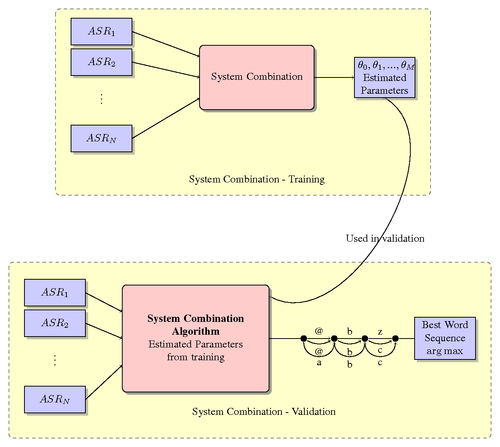
A block diagram of system combination technique of combining several Automatic Speech Recognition Systems (ASRs) to determine best word sequence outputs is shown here. The training and validation phase are the important phases.
Edit and compile if you like:
% System Combination % Harish K Krishnamurthy\documentclass{article} \usepackage{tikz} \usetikzlibrary{shapes,arrows,shadows} \usepackage{amsmath,bm,times} \usepackage[active,tightpage]{preview} \PreviewEnvironment{tikzpicture} \setlength\PreviewBorder{5pt}% \newcommand{\mx}[1]{\mathbf{\bm{#1}}} % Matrix command \newcommand{\vc}[1]{\mathbf{\bm{#1}}} % Vector command \begin{document} % Define the layers to draw the diagram \pgfdeclarelayer{background} \pgfdeclarelayer{foreground} \pgfsetlayers{background,main,foreground} % Define block styles used later \tikzstyle{sensor}=[draw, fill=blue!20, text width=5em, text centered, minimum height=2.5em,drop shadow] \tikzstyle{ann} = [above, text width=5em, text centered] \tikzstyle{wa} = [sensor, text width=10em, fill=red!20, minimum height=6em, rounded corners, drop shadow] \tikzstyle{sc} = [sensor, text width=13em, fill=red!20, minimum height=10em, rounded corners, drop shadow] % Define distances for bordering \def\blockdist{2.3} \def\edgedist{2.5} \begin{tikzpicture} \node (wa) [wa] {System Combination}; \path (wa.west)+(-3.2,1.5) node (asr1) [sensor] {$ASR_1$}; \path (wa.west)+(-3.2,0.5) node (asr2)[sensor] {$ASR_2$}; \path (wa.west)+(-3.2,-1.0) node (dots)[ann] {$\vdots$}; \path (wa.west)+(-3.2,-2.0) node (asr3)[sensor] {$ASR_N$}; \path (wa.east)+(\blockdist,0) node (vote) [sensor] {$\theta_0,\theta_1,...,\theta_M$\\Estimated Parameters}; \path [draw, ->] (asr1.east) -- node [above] {} (wa.160) ; \path [draw, ->] (asr2.east) -- node [above] {} (wa.180); \path [draw, ->] (asr3.east) -- node [above] {} (wa.200); \path [draw, ->] (wa.east) -- node [above] {} (vote.west); \path (wa.south) +(0,-\blockdist) node (asrs) {System Combination - Training}; \begin{pgfonlayer}{background} \path (asr1.west |- asr1.north)+(-0.5,0.3) node (a) {}; \path (wa.south -| wa.east)+(+0.5,-0.3) node (b) {}; \path (vote.east |- asrs.east)+(+0.5,-0.5) node (c) {}; \path[fill=yellow!20,rounded corners, draw=black!50, dashed] (a) rectangle (c); \path (asr1.north west)+(-0.2,0.2) node (a) {}; \end{pgfonlayer} % Validation Layer is the same except that there are a set of nodes and links which are added \path (wa.south)+(-2.0,-7.5) node (syscomb) [sc] {\textbf{System Combination \\Algorithm}\\Estimated Parameters\\from training}; \path (syscomb.west)+(-2.2,1.5) node (asrt1) [sensor] {$ASR_1$}; \path (syscomb.west)+(-2.2,0.5) node (asrt2)[sensor] {$ASR_2$}; \path (syscomb.west)+(-2.2,-1.0) node (dots)[ann] {$\vdots$}; \path (syscomb.west)+(-2.2,-2.0) node (asrt3)[sensor] {$ASR_N$}; \path [draw, ->] (asrt1.east) -- node [above] {} (syscomb.160) ; \path [draw, ->] (asrt2.east) -- node [above] {} (syscomb.180); \path [draw, ->] (asrt3.east) -- node [above] {} (syscomb.200); \path (wa.south) +(0,-\blockdist) node (sct) {System Combination - Training}; \path (syscomb.east)+(1.0,0.0) node (bwtn) {}; % Note how the single nodes are repeated using for loop \foreach \x in {0,1,...,4} { \draw (bwtn.east)+(\x,0) node (asr\x-2)[]{}; \fill (bwtn.east)+(\x,0) circle (0.1cm); } \path [draw, ->] (syscomb.east) -- node [above] {} (bwtn.east); \path [draw, ->] (asr0-2) -- node [above] {@} (asr1-2); \path [draw, -] (asr1-2) -- node [above] {b} (asr2-2); \path [draw, -] (asr2-2) -- node [above] {z} (asr3-2); \path [draw, -] (asr3-2) -- node [above] {} (asr4-2); \path [draw, ->] (asr0-2) edge[bend right] node [below] {@} (asr1-2); \path [draw, ->] (asr1-2) edge[bend right] node [below] {b} (asr2-2); \path [draw, ->] (asr2-2) edge[bend right] node [below] {c} (asr3-2); \path [draw, ->] (asr4-2) node[]{} (asr4-2)+(1.0,0); \begin{scope}[looseness=1.6] \path [draw, ->] (asr0-2) edge[bend right=90] node [below] {a} (asr1-2); \path [draw, ->] (asr1-2) edge[bend right=90] node [below] {b} (asr2-2); \path [draw, ->] (asr2-2) edge[bend right=90] node [below] {c} (asr3-2); \end{scope} \path (asr3-2.east)+(1.5,0.0) node (bw)[sensor] {Best Word Sequence\\$\arg\max$}; \path [draw, -] (asr1-2.east) node [below] {} (bw.west); \begin{pgfonlayer}{background} \path (asrt1.west)+(-0.5,1.0) node (g) {}; \path (bw.east |- syscomb.south)+(0.5,-1.5) node (h) {}; \path[fill=yellow!20,rounded corners, draw=black!50, dashed] (g) rectangle (h); \path [draw, ->] (vote.south) edge[bend left=90] node [below] {Used in validation} (syscomb.30); \end{pgfonlayer} \path (asr1-2.south) +(-\blockdist,-\blockdist) node (asrs) {System Combination - Validation}; \end{tikzpicture} \end{document}
Click to download: system-combination.tex • system-combination.pdf
Open in Overleaf: system-combination.tex