


Three-tier data center architecture. The reference was Figure 3-8 Three-Tie Model with 8-Way ECMP of Cisco Data Center Infrastructure 2.5 Design Guide.
This code was written by Claudio Fiandrino and published on TeX.SE.
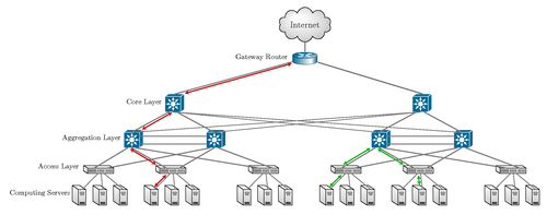
Edit and compile if you like:
% Three-tier data center architecture
% Author: Claudio Fiandrino
\documentclass{article}
\usepackage{tikz}
\usepackage[a4paper,landscape,hmargin={1cm,1cm}]{geometry}
\usepackage[active,tightpage]{preview}
\PreviewEnvironment{tikzpicture}
\setlength\PreviewBorder{10pt}%
\usetikzlibrary{backgrounds,calc,shadings,shapes.arrows,shapes.symbols,shadows}
\definecolor{switch}{HTML}{006996}

\makeatletter
\pgfkeys{/pgf/.cd,
  parallelepiped offset x/.initial=2mm,
  parallelepiped offset y/.initial=2mm
}
\pgfdeclareshape{parallelepiped}
{
  \inheritsavedanchors[from=rectangle] % this is nearly a rectangle
  \inheritanchorborder[from=rectangle]
  \inheritanchor[from=rectangle]{north}
  \inheritanchor[from=rectangle]{north west}
  \inheritanchor[from=rectangle]{north east}
  \inheritanchor[from=rectangle]{center}
  \inheritanchor[from=rectangle]{west}
  \inheritanchor[from=rectangle]{east}
  \inheritanchor[from=rectangle]{mid}
  \inheritanchor[from=rectangle]{mid west}
  \inheritanchor[from=rectangle]{mid east}
  \inheritanchor[from=rectangle]{base}
  \inheritanchor[from=rectangle]{base west}
  \inheritanchor[from=rectangle]{base east}
  \inheritanchor[from=rectangle]{south}
  \inheritanchor[from=rectangle]{south west}
  \inheritanchor[from=rectangle]{south east}
  \backgroundpath{
    % store lower right in xa/ya and upper right in xb/yb
    \southwest \pgf@xa=\pgf@x \pgf@ya=\pgf@y
    \northeast \pgf@xb=\pgf@x \pgf@yb=\pgf@y
    \pgfmathsetlength\pgfutil@tempdima{\pgfkeysvalueof{/pgf/parallelepiped
      offset x}}
    \pgfmathsetlength\pgfutil@tempdimb{\pgfkeysvalueof{/pgf/parallelepiped
      offset y}}
    \def\ppd@offset{\pgfpoint{\pgfutil@tempdima}{\pgfutil@tempdimb}}
    \pgfpathmoveto{\pgfqpoint{\pgf@xa}{\pgf@ya}}
    \pgfpathlineto{\pgfqpoint{\pgf@xb}{\pgf@ya}}
    \pgfpathlineto{\pgfqpoint{\pgf@xb}{\pgf@yb}}
    \pgfpathlineto{\pgfqpoint{\pgf@xa}{\pgf@yb}}
    \pgfpathclose
    \pgfpathmoveto{\pgfqpoint{\pgf@xb}{\pgf@ya}}
    \pgfpathlineto{\pgfpointadd{\pgfpoint{\pgf@xb}{\pgf@ya}}{\ppd@offset}}
    \pgfpathlineto{\pgfpointadd{\pgfpoint{\pgf@xb}{\pgf@yb}}{\ppd@offset}}
    \pgfpathlineto{\pgfpointadd{\pgfpoint{\pgf@xa}{\pgf@yb}}{\ppd@offset}}
    \pgfpathlineto{\pgfqpoint{\pgf@xa}{\pgf@yb}}
    \pgfpathmoveto{\pgfqpoint{\pgf@xb}{\pgf@yb}}
    \pgfpathlineto{\pgfpointadd{\pgfpoint{\pgf@xb}{\pgf@yb}}{\ppd@offset}}
  }
}
\makeatother

\tikzset{l3 switch/.style={
    parallelepiped,fill=switch, draw=white,
    minimum width=0.75cm,
    minimum height=0.75cm,
    parallelepiped offset x=1.75mm,
    parallelepiped offset y=1.25mm,
    path picture={
      \node[fill=white,
        circle,
        minimum size=6pt,
        inner sep=0pt,
        append after command={
          \pgfextra{
            \foreach \angle in {0,45,...,360}
            \draw[-latex,fill=white] (\tikzlastnode.\angle)--++(\angle:2.25mm);
          }
        }
      ]
       at ([xshift=-0.75mm,yshift=-0.5mm]path picture bounding box.center){};
    }
  },
  ports/.style={
    line width=0.3pt,
    top color=gray!20,
    bottom color=gray!80
  },
  rack switch/.style={
    parallelepiped,fill=white, draw,
    minimum width=1.25cm,
    minimum height=0.25cm,
    parallelepiped offset x=2mm,
    parallelepiped offset y=1.25mm,
    xscale=-1,
    path picture={
      \draw[top color=gray!5,bottom color=gray!40]
      (path picture bounding box.south west) rectangle
      (path picture bounding box.north east);
      \coordinate (A-west) at ([xshift=-0.2cm]path picture bounding box.west);
      \coordinate (A-center) at ($(path picture bounding box.center)!0!(path
        picture bounding box.south)$);
      \foreach \x in {0.275,0.525,0.775}{
        \draw[ports]([yshift=-0.05cm]$(A-west)!\x!(A-center)$)
          rectangle +(0.1,0.05);
        \draw[ports]([yshift=-0.125cm]$(A-west)!\x!(A-center)$)
          rectangle +(0.1,0.05);
       }
      \coordinate (A-east) at (path picture bounding box.east);
      \foreach \x in {0.085,0.21,0.335,0.455,0.635,0.755,0.875,1}{
        \draw[ports]([yshift=-0.1125cm]$(A-east)!\x!(A-center)$)
          rectangle +(0.05,0.1);
      }
    }
  },
  server/.style={
    parallelepiped,
    fill=white, draw,
    minimum width=0.35cm,
    minimum height=0.75cm,
    parallelepiped offset x=3mm,
    parallelepiped offset y=2mm,
    xscale=-1,
    path picture={
      \draw[top color=gray!5,bottom color=gray!40]
      (path picture bounding box.south west) rectangle
      (path picture bounding box.north east);
      \coordinate (A-center) at ($(path picture bounding box.center)!0!(path
        picture bounding box.south)$);
      \coordinate (A-west) at ([xshift=-0.575cm]path picture bounding box.west);
      \draw[ports]([yshift=0.1cm]$(A-west)!0!(A-center)$)
        rectangle +(0.2,0.065);
      \draw[ports]([yshift=0.01cm]$(A-west)!0.085!(A-center)$)
        rectangle +(0.15,0.05);
      \fill[black]([yshift=-0.35cm]$(A-west)!-0.1!(A-center)$)
        rectangle +(0.235,0.0175);
      \fill[black]([yshift=-0.385cm]$(A-west)!-0.1!(A-center)$)
        rectangle +(0.235,0.0175);
      \fill[black]([yshift=-0.42cm]$(A-west)!-0.1!(A-center)$)
        rectangle +(0.235,0.0175);
    }
  },
}

\usetikzlibrary{calc, shadings, shadows, shapes.arrows}

% Styles for interfaces and edge labels
\tikzset{%
  interface/.style={draw, rectangle, rounded corners, font=\LARGE\sffamily},
  ethernet/.style={interface, fill=yellow!50},% ethernet interface
  serial/.style={interface, fill=green!70},% serial interface
  speed/.style={sloped, anchor=south, font=\large\sffamily},% line speed at edge
  route/.style={draw, shape=single arrow, single arrow head extend=4mm,
    minimum height=1.7cm, minimum width=3mm, white, fill=switch!20,
    drop shadow={opacity=.8, fill=switch}, font=\tiny}% inroute/outroute arrows
}
\newcommand*{\shift}{1.3cm}% For placing the arrows later

% The router icon
\newcommand*{\router}[1]{
\begin{tikzpicture}
  \coordinate (ll) at (-3,0.5);
  \coordinate (lr) at (3,0.5);
  \coordinate (ul) at (-3,2);
  \coordinate (ur) at (3,2);
  \shade [shading angle=90, left color=switch, right color=white] (ll)
    arc (-180:-60:3cm and .75cm) -- +(0,1.5) arc (-60:-180:3cm and .75cm)
    -- cycle;
  \shade [shading angle=270, right color=switch, left color=white!50] (lr)
    arc (0:-60:3cm and .75cm) -- +(0,1.5) arc (-60:0:3cm and .75cm) -- cycle;
  \draw [thick] (ll) arc (-180:0:3cm and .75cm)
    -- (ur) arc (0:-180:3cm and .75cm) -- cycle;
  \draw [thick, shade, upper left=switch, lower left=switch,
    upper right=switch, lower right=white] (ul)
    arc (-180:180:3cm and .75cm);
  \node at (0,0.5){\color{blue!60!black}\Huge #1};% The name of the router
  % The four arrows, symbols for incoming and outgoing routes:
  \begin{scope}[yshift=2cm, yscale=0.28, transform shape]
    \node[route, rotate=45, xshift=\shift] {\strut};
    \node[route, rotate=-45, xshift=-\shift] {\strut};
    \node[route, rotate=-135, xshift=\shift] {\strut};
    \node[route, rotate=135, xshift=-\shift] {\strut};
  \end{scope}
\end{tikzpicture}}

\makeatletter
\pgfdeclareradialshading[tikz@ball]{cloud}{\pgfpoint{-0.275cm}{0.4cm}}{%
  color(0cm)=(tikz@ball!75!white);
  color(0.1cm)=(tikz@ball!85!white);
  color(0.2cm)=(tikz@ball!95!white);
  color(0.7cm)=(tikz@ball!89!black);
  color(1cm)=(tikz@ball!75!black)
}
\tikzoption{cloud color}{\pgfutil@colorlet{tikz@ball}{#1}%
  \def\tikz@shading{cloud}\tikz@addmode{\tikz@mode@shadetrue}}
\makeatother

\tikzset{my cloud/.style={
     cloud, draw, aspect=2,
     cloud color={gray!5!white}
  }
}

\begin{document}

\begin{tikzpicture}

\node[server](server 1){};
\node[server, right of= server 1](server 2){};
\node[server, right of= server 2](server 3){};

\node[rack switch, above of=server 2,xshift=0.1cm,yshift=0.3cm]
  (rack switch 1){};

\draw[thick,darkgray!10!gray] (server 1.north)--(rack switch 1);
\draw[thick,darkgray!10!gray] (server 2.north)--(rack switch 1);
\draw[thick,darkgray!10!gray] (server 3.north)--(rack switch 1);

\begin{scope}[xshift=3.5cm]
  \node[server](server 4){};
  \node[server, right of= server 4](server 5){};
  \node[server, right of= server 5](server 6){};

  \node[rack switch, above of=server 5,xshift=0.1cm,yshift=0.3cm]
  (rack switch 2){};

  \draw[thick,darkgray!10!gray] (server 4.north)--(rack switch 2);
  \draw[thick,darkgray!10!gray] (server 5.north)--(rack switch 2);
  \draw[thick,darkgray!10!gray] (server 6.north)--(rack switch 2);
\end{scope}

\begin{scope}[xshift=8cm]
  \node[server](server 7){};
  \node[server, right of= server 7](server 8){};
  \node[server, right of= server 8](server 9){};

  \node[rack switch, above of=server 8,xshift=0.1cm,yshift=0.3cm]
  (rack switch 3){};

  \draw[thick,darkgray!10!gray] (server 7.north)--(rack switch 3);
  \draw[thick,darkgray!10!gray] (server 8.north)--(rack switch 3);
  \draw[thick,darkgray!10!gray] (server 9.north)--(rack switch 3);
\end{scope}


\node[l3 switch, above of =rack switch 1, xshift=1.5cm,yshift=0.5cm]
  (l3 switch 1){};
\node[l3 switch, above of =rack switch 2, xshift=2cm,yshift=0.5cm]
  (l3 switch 2){};

\begin{scope}[very thick,darkgray!10!gray]
  \draw ($(rack switch 1.north)!0.5!(rack switch 1.north west)$)--
   ($(l3 switch 2.south)!0.5!(l3 switch 2.south west)$);
  \draw ($(rack switch 1.north)!0.5!(rack switch 1.north east)$)--
   ($(l3 switch 1.south)!0.5!(l3 switch 1.south west)$);

  \draw ($(rack switch 2.north)!0.5!(rack switch 2.north west)$)--
   ($(l3 switch 2.south)!0!(l3 switch 2.south west)$);
  \draw ($(rack switch 2.north)!0.5!(rack switch 2.north east)$)--
   ($(l3 switch 1.south)!0!(l3 switch 1.south west)$);

  \draw ($(rack switch 3.north)!0.5!(rack switch 3.north west)$)--
   ($(l3 switch 2.south)!0.5!(l3 switch 2.south east)$);
  \draw ($(rack switch 3.north)!0.5!(rack switch 3.north east)$)--
   ($(l3 switch 1.south)!0.5!(l3 switch 1.south east)$);

  \draw ($(l3 switch 2.north west)!0.25!(l3 switch 2.south west)$)--
  ($(l3 switch 1.north east)!0.25!(l3 switch 1.south east)$);

  \draw ($(l3 switch 2.north west)!0.75!(l3 switch 2.south west)$)--
  ($(l3 switch 1.north east)!0.75!(l3 switch 1.south east)$);

\end{scope}

\node[l3 switch, above of =l3 switch 1, xshift=2cm,yshift=0.75cm](border 1){};

% = = = = = = = = = = = = = = = =
% Labels
% = = = = = = = = = = = = = = = =


\node[xshift=-1.05cm,yshift=0.2cm,left of = server 3,align=left](lev1)
  {Computing Servers};

\node[xshift=0.9cm,yshift=0.3cm,above of = lev1,align=left](lev2)
  {Access Layer};

\node[xshift=1.6cm,yshift=0.4cm,above of = lev2,align=left](lev3)
  {Aggregation Layer};
\node[xshift=2.55cm,yshift=0.75cm,above of = lev3,align=right](lev4)
  {Core Layer};
\node[xshift=5.7cm,yshift=1.2cm,above of = lev4,align=right](lev5)
  {Gateway Router};

% = = = = = = = = = = = = = = = =
% Shifted part
% = = = = = = = = = = = = = = = =

\begin{scope}[xshift=12cm]
  \node[server](server 1-a){};
  \node[server, right of= server 1-a](server 2-a){};
  \node[server, right of= server 2-a](server 3-a){};

  \node[rack switch, above of=server 2-a,xshift=0.1cm,yshift=0.3cm]
    (rack switch 1-a){};

  \draw[thick,darkgray!10!gray] (server 1-a.north)--(rack switch 1-a);
  \draw[thick,darkgray!10!gray] (server 2-a.north)--(rack switch 1-a);
  \draw[thick,darkgray!10!gray] (server 3-a.north)--(rack switch 1-a);

  \begin{scope}[xshift=3.5cm]
    \node[server](server 4-a){};
    \node[server, right of= server 4-a](server 5-a){};
    \node[server, right of= server 5-a](server 6-a){};

    \node[rack switch, above of=server 5-a,xshift=0.1cm,yshift=0.3cm]
      (rack switch 2-a){};

    \draw[thick,darkgray!10!gray] (server 4-a.north)--(rack switch 2-a);
    \draw[thick,darkgray!10!gray] (server 5-a.north)--(rack switch 2-a);
    \draw[thick,darkgray!10!gray] (server 6-a.north)--(rack switch 2-a);
  \end{scope}

  \begin{scope}[xshift=8cm]
    \node[server](server 7-a){};
    \node[server, right of= server 7-a](server 8-a){};
    \node[server, right of= server 8-a](server 9-a){};

    \node[rack switch, above of=server 8-a,xshift=0.1cm,yshift=0.3cm]
      (rack switch 3-a){};

    \draw[thick,darkgray!10!gray] (server 7-a.north)--(rack switch 3-a);
    \draw[thick,darkgray!10!gray] (server 8-a.north)--(rack switch 3-a);
    \draw[thick,darkgray!10!gray] (server 9-a.north)--(rack switch 3-a);
  \end{scope}


  \node[l3 switch, above of =rack switch 1-a, xshift=1.5cm,yshift=0.5cm]
    (l3 switch 1-a){};
  \node[l3 switch, above of =rack switch 2-a, xshift=2cm,yshift=0.5cm]
    (l3 switch 2-a){};

  \begin{scope}[very thick,darkgray!10!gray]
    \draw ($(rack switch 1-a.north)!0.5!(rack switch 1-a.north west)$)--
     ($(l3 switch 2-a.south)!0.5!(l3 switch 2-a.south west)$);
    \draw ($(rack switch 1-a.north)!0.5!(rack switch 1-a.north east)$)--
     ($(l3 switch 1-a.south)!0.5!(l3 switch 1-a.south west)$);

    \draw ($(rack switch 2-a.north)!0.5!(rack switch 2-a.north west)$)--
     ($(l3 switch 2-a.south)!0!(l3 switch 2-a.south west)$);
    \draw ($(rack switch 2-a.north)!0.5!(rack switch 2-a.north east)$)--
     ($(l3 switch 1-a.south)!0!(l3 switch 1-a.south west)$);

    \draw ($(rack switch 3-a.north)!0.5!(rack switch 3-a.north west)$)--
     ($(l3 switch 2-a.south)!0.5!(l3 switch 2-a.south east)$);
    \draw ($(rack switch 3-a.north)!0.5!(rack switch 3-a.north east)$)--
     ($(l3 switch 1-a.south)!0.5!(l3 switch 1-a.south east)$);

    \draw ($(l3 switch 2-a.north west)!0.25!(l3 switch 2-a.south west)$)--
    ($(l3 switch 1-a.north east)!0.25!(l3 switch 1-a.south east)$);

    \draw ($(l3 switch 2-a.north west)!0.75!(l3 switch 2-a.south west)$)--
    ($(l3 switch 1-a.north east)!0.75!(l3 switch 1-a.south east)$);

  \end{scope}

  \node[l3 switch, above of =l3 switch 1-a, xshift=2cm,yshift=0.75cm]
    (border 1-a){};

  \begin{scope}[very thick,darkgray!10!gray]
    \draw ($(border 1-a.south)!0.5!(border 1-a.south west)$)--
     (l3 switch 1-a.north);

    \draw[thick] (border 1-a.south)--
     ([xshift=0.1cm]l3 switch 1.north);

    \draw ($(border 1-a.south)!-0.5!(border 1-a.south west)$)--
      (l3 switch 2-a.north);

    \draw[thick] (border 1-a.south)--([xshift=0.05cm]l3 switch 2.north);
  \end{scope}
\end{scope}


% = = = = = = = = = = = = = = = =
% Background rectangle - removed
% = = = = = = = = = = = = = = = =

\path ($(server 3.south west)!0.9!(lev1.south east)-(0,0.4cm)$) coordinate (A)
  --([yshift=0.86cm]A |- lev4.north east)coordinate (B)--
  ($(B)+(11.2cm,0)$)coordinate (C);

% = = = = = = = = = = = = = = = =
% Border Router and Internet
% = = = = = = = = = = = = = = = =

% interconnections of border 1
\begin{scope}[very thick,darkgray!10!gray]
  \draw ($(border 1.south)!0.5!(border 1.south west)$)--
   (l3 switch 1.north);

  \draw[thick] (border 1.south)--
   ([xshift=-0.05cm]l3 switch 1-a.north);

  \draw ($(border 1.south)!-0.5!(border 1.south west)$)--
   (l3 switch 2.north);

  \draw[thick] (border 1.south)--
   ([xshift=-0.1cm]l3 switch 2-a.north);
\end{scope}

\begin{scope}
  \node[yshift=1cm,scale=0.2] (brouter) at (C) {\router{}}
    edge[very thick,darkgray!10!gray] ([xshift=0.1cm,yshift=0.5cm]border 1);

  \node[yshift=0.65cm,my cloud, minimum width=1.25cm, minimum height=1.55cm,
    above of=brouter,font=\large] (it) {Internet}
      edge[very thick,darkgray!30!gray] (brouter);
  \draw[very thick,darkgray!30!gray](brouter)--
    ([xshift=0.1cm,yshift=0.125cm]border 1-a.north);
\end{scope}

% = = = = = = = = = = = = = = = =
% paths
% = = = = = = = = = = = = = = = =

% paths: north-south
\draw[stealth-stealth,very thick, red!80!black,shorten <=0.025cm,
  shorten >=0.56cm]([yshift=-0.25cm]brouter.west)--
  ([xshift=0.05cm]border 1.north);

\draw[stealth-stealth,very thick, red!80!black,shorten <=0.05cm,
  shorten >=0.125cm] (border 1.south)--
  ([yshift=0.075cm,xshift=0.4cm]l3 switch 1.north);

\draw[stealth-stealth,very thick, red!80!black,shorten <=0.1cm, shorten >=0.2cm]
  ([xshift=-0.15cm]l3 switch 1.south)--
  ([yshift=0.075cm,xshift=-0.65cm]rack switch 2.north);

\draw[stealth-stealth,very thick, red!80!black,shorten <=0.1cm, shorten >=0.1cm]
  ([xshift=-0.25cm]rack switch 2.south)--
  ([yshift=0.075cm,xshift=-0.06cm]server 6.north);

% paths: east-west
\draw[stealth-stealth,very thick, green!70!black,shorten <=0.1cm,
  shorten >=0.1cm] ([xshift=-0.25cm]rack switch 1-a.south)--
  ([yshift=0.075cm,xshift=-0.06cm]server 3-a.north);

\draw[stealth-stealth,very thick, green!70!black,shorten <=0.025cm,
  shorten >=0.2cm] ([xshift=-0.4cm]l3 switch 1-a.south)--
  ([yshift=0.075cm,xshift=-0.4cm]rack switch 1-a.north);

\draw[stealth-stealth, very thick, green!70!black,shorten <=0.1cm,
  shorten >=0.2cm] ([xshift=-0.15cm]l3 switch 1-a.south)--
  ([yshift=0.075cm,xshift=-0.65cm]rack switch 2-a.north);

\draw[stealth-stealth,very thick, green!70!black,shorten <=0.1cm,
  shorten >=0.15cm] ([xshift=-0.1cm]rack switch 2-a.south)--
  ([yshift=0.075cm,xshift=-0.12cm]server 5-a.north);

\end{tikzpicture}

\end{document}
Click to download: network-topology.tex • network-topology.pdf
Open in Overleaf: network-topology.tex