


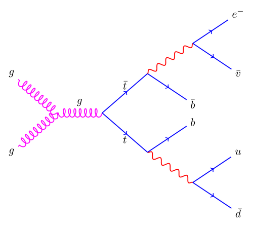
I saw this Feynman diagram in Edward Tufte's book Beautiful evidence (you can also find it in this thread). It was relatively easy to recreate using trees and decorations.
Update: Rewritten using PGF 2.0 features.
Edit and compile if you like:
% Feynman diagram
% Requires PGF >= 2.0
\documentclass{article}

\usepackage[latin1]{inputenc}
\usepackage{tikz}
\usetikzlibrary{trees}
\usetikzlibrary{decorations.pathmorphing}
\usetikzlibrary{decorations.markings}


\begin{document}

% Define styles for the different kind of edges in a Feynman diagram
\tikzset{
    photon/.style={decorate, decoration={snake}, draw=red},
    electron/.style={draw=blue, postaction={decorate},
        decoration={markings,mark=at position .55 with {\arrow[draw=blue]{>}}}},
    gluon/.style={decorate, draw=magenta,
        decoration={coil,amplitude=4pt, segment length=5pt}}
}

\begin{tikzpicture}[
        thick,
        % Set the overall layout of the tree
        level/.style={level distance=1.5cm},
        level 2/.style={sibling distance=2.6cm},
        level 3/.style={sibling distance=2cm}
    ]
    \coordinate
        child[grow=left]{
            child {
                node {$g$}
                % The 'edge from parent' is actually not needed because it is
                % implicitly added.
                edge from parent [gluon]
            }
            child {
                node {$g$}
                edge from parent [gluon]
            }
            edge from parent [gluon] node [above=3pt] {$g$}
        }
        % I have to insert a dummy child to get the tree to grow
        % correctly to the right.
        child[grow=right, level distance=0pt] {
        child  {
            child {
                child {
                    node {$\bar{d}$}
                    edge from parent [electron]
                }
                child {
                    node {$u$}
                    edge from parent [electron]
                }
                edge from parent [photon]
            }
            child {
                node {$b$}
                edge from parent [electron]
            }
            edge from parent [electron]
            node [below] {$t$}
        }
        child {
            child {
                node {$\bar{b}$}
                edge from parent [electron]
            }
            child {
                child {
                    node {$\bar{v}$}
                    edge from parent [electron]
                }
                child {
                    node {$e^{-}$}
                    edge from parent [electron]
                }
                edge from parent [photon]
            }
            edge from parent [electron]
            node [above] {$\bar{t}$}
        }
    };
\end{tikzpicture}


\end{document}
Click to download: feynman-diagram.tex • feynman-diagram.pdf
Open in Overleaf: feynman-diagram.tex