


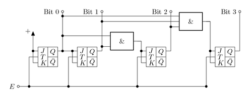
The circuitikz package provides macros for typesetting electrical and electronical networks. Here it's used to draw a 4-bit counter circuit. It's a synchronous counter, i.e. the circuit is synchronized by a clock signal. The counter is built using JK-flip-flops. A flip-flop is is a circuit with two stable states, useful for storing state information.
Edit and compile if you like:
% Synchronous 4-bit counter circuit using JK-flip-flops
% Author: Henri Menke
\documentclass{article}
\usepackage{tikz}
\usepackage[active,tightpage]{preview}
\PreviewEnvironment{tikzpicture}
\setlength\PreviewBorder{10pt}%
\usetikzlibrary{calc,arrows}
\usepackage[european]{circuitikz}
\begin{document}
\def\JKFF(#1)#2#3{%
  \begin{scope}[shift={(#1)}]
    \draw (0,0) rectangle (1,1);
    \draw (0.5,1) -- (0.5,0);
    \draw (0.5,0.5) -- (1,0.5);
    \node at (0.75,0.75) {$Q$};
    \node at (0.75,0.25) {$\bar{Q}$};
    \draw (1,0.8) -- +(0.25,0) coordinate (#2 Q);
    \draw (0,0.2) node[right] {$K$} -- +(-0.25,0) coordinate (#2 K);
    \draw (0,0.5) node[right] {$T$} -- +(-0.25,0) coordinate (#2 T);
    \draw (0,0.8) node[right] {$J$} -- +(-0.25,0) coordinate (#2 J);
  \end{scope}
}
\begin{tikzpicture}[every path/.style={},>=triangle 45]
    % Place the JK-Flip-Flops
  \JKFF(0,0){a}{$Q_0$}
  \JKFF(2,0){b}{$Q_1$}
  \JKFF(5.5,0){c}{$Q_2$}
  \JKFF(9,0){d}{$Q_3$}
  % Connect all the K and J ports
  \draw (a K) to[short,-*] (a J);
  \draw (b K) to[short,-*] (b J);
  \draw (c K) to[short,-*] (c J);
  \draw (d K) to[short,-*] (d J);
  % Connect the T ports to the incoming signal
  \draw (-1,-1) node[ocirc,label={left:$E$}] (E) {};
  \draw (a T) -- ++(-0.2,0) coordinate (inter) -|
    (E -| inter) node[circ] {};
  \draw (b T) -- ++(-0.2,0) coordinate (inter) -|
    (E -| inter) node[circ] {};
  \draw (c T) -- ++(-0.2,0) coordinate (inter) -|
    (E -| inter) node[circ] {};
  \draw (d T) -- ++(-0.2,0) coordinate (inter) -|
    (E -| inter) node[circ] {} -- (E);
  % Place the bits and the +
  \draw[->] (a J) -- ++(0,1) node[left] {$+$};
  \draw (a Q) to[short] ++(0,2) node[ocirc,label={left:Bit 0}] (bit0) {};
  \draw (b Q) to[short] ++(0,2) node[ocirc,label={left:Bit 1}] (bit1) {};
  \draw (c Q) to[short] ++(0,2) node[ocirc,label={left:Bit 2}] (bit2) {};
  \draw (d Q) to[short] ++(0,2) node[ocirc,label={left:Bit 3}] (bit3) {};
  % AND ports
  \draw (c J) |- ++(-0.2,0.5) node[and port] (c and) {};
  \draw (d J) |- ++(-0.2,1.5) node[and port] (d and) {};
  % Output connections
  \draw (b J) to[short,-*] (a Q);
  \draw (c and.in 2) to[short,-*] (c and.in 2 -| bit1);
  \draw (c and.in 1) to[short,-*] (c and.in 1 -| bit0);
  \draw (d and.in 2) to[short,-*] (d and.in 2 -| bit2);
  \draw (d and.in 1) to[short,-*] (d and.in 1 -| bit0);
  % I had to guess this connection, because the and port doesn't
  % have additional anchors
  \draw ($(d and.in 2)!0.5!(d and.in 1)+(0.4,0)$) coordinate (help)
    to[short,-*] (help -| bit1);
\end{tikzpicture}
\end{document}
Click to download: 4-bit-counter.tex • 4-bit-counter.pdf
Open in Overleaf: 4-bit-counter.tex