")


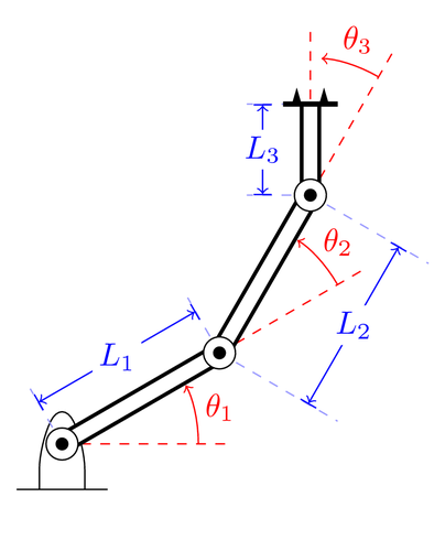
This example shows how you can annotate a technical drawing. The three link manipulator is the same as another example in the gallery. I've used macros extensively to avoid duplicating code.
Edit and compile if you like:
\documentclass{article}

\usepackage[latin1]{inputenc}
\usepackage{tikz}
\usetikzlibrary{patterns}


\begin{document}
\pagestyle{empty}

% Note. This illustration was originally made with PSTricks. Conversion to
% PGF/TikZ was straightforward. However, I could probably have made it more
% elegant.

% Define a variable as a length
% Input:
%   #1 Variable name
%   #2 Value
%
% Example:
%   \nvar{\varx}{2cm}
\newcommand{\nvar}[2]{%
    \newlength{#1}
    \setlength{#1}{#2}
}

% Define a few constants for drawing
\nvar{\dg}{0.3cm}
\def\dw{0.25}\def\dh{0.5}
\nvar{\ddx}{1.5cm}

% Define commands for links, joints and such
\def\link{\draw [double distance=1.5mm, very thick] (0,0)--}
\def\joint{%
    \filldraw [fill=white] (0,0) circle (5pt);
    \fill[black] circle (2pt);
}
\def\grip{%
    \draw[ultra thick](0cm,\dg)--(0cm,-\dg);
    \fill (0cm, 0.5\dg)+(0cm,1.5pt) -- +(0.6\dg,0cm) -- +(0pt,-1.5pt);
    \fill (0cm, -0.5\dg)+(0cm,1.5pt) -- +(0.6\dg,0cm) -- +(0pt,-1.5pt);
}
\def\robotbase{%
    \draw[rounded corners=8pt] (-\dw,-\dh)-- (-\dw, 0) --
        (0,\dh)--(\dw,0)--(\dw,-\dh);
    \draw (-0.5,-\dh)-- (0.5,-\dh);
    \fill[pattern=north east lines] (-0.5,-1) rectangle (0.5,-\dh);
}

% Draw an angle annotation
% Input:
%   #1 Angle
%   #2 Label
% Example:
%   \angann{30}{$\theta_1$}
\newcommand{\angann}[2]{%
    \begin{scope}[red]
    \draw [dashed, red] (0,0) -- (1.2\ddx,0pt);
    \draw [->, shorten >=3.5pt] (\ddx,0pt) arc (0:#1:\ddx);
    % Unfortunately automatic node placement on an arc is not supported yet.
    % We therefore have to compute an appropriate coordinate ourselves.
    \node at (#1/2-2:\ddx+8pt) {#2};
    \end{scope}
}

% Draw line annotation
% Input:
%   #1 Line offset (optional)
%   #2 Line angle
%   #3 Line length
%   #5 Line label
% Example:
%   \lineann[1]{30}{2}{$L_1$}
\newcommand{\lineann}[4][0.5]{%
    \begin{scope}[rotate=#2, blue,inner sep=2pt]
        \draw[dashed, blue!40] (0,0) -- +(0,#1)
            node [coordinate, near end] (a) {};
        \draw[dashed, blue!40] (#3,0) -- +(0,#1)
            node [coordinate, near end] (b) {};
        \draw[|<->|] (a) -- node[fill=white] {#4} (b);
    \end{scope}
}

% Define the kinematic parameters of the three link manipulator.
\def\thetaone{30}
\def\Lone{2}
\def\thetatwo{30}
\def\Ltwo{2}
\def\thetathree{30}
\def\Lthree{1}

\begin{tikzpicture}
    \robotbase
    \angann{\thetaone}{$\theta_1$}
    \lineann[0.7]{\thetaone}{\Lone}{$L_1$}
    \link(\thetaone:\Lone);
    \joint
    \begin{scope}[shift=(\thetaone:\Lone), rotate=\thetaone]
        \angann{\thetatwo}{$\theta_2$}
        \lineann[-1.5]{\thetatwo}{\Ltwo}{$L_2$}
        \link(\thetatwo:\Ltwo);
        \joint
        \begin{scope}[shift=(\thetatwo:\Ltwo), rotate=\thetatwo]
            \angann{\thetathree}{$\theta_3$}
            \lineann[0.7]{\thetathree}{\Lthree}{$L_3$}
            \draw [dashed, red,rotate=\thetathree] (0,0) -- (1.2\ddx,0pt);
            \link(\thetathree:\Lthree);
            \joint
            \begin{scope}[shift=(\thetathree:\Lthree), rotate=\thetathree]
                \grip
            \end{scope}
        \end{scope}
    \end{scope}
\end{tikzpicture}


\end{document}
Click to download: three-link-annotated.tex • three-link-annotated.pdf
Open in Overleaf: three-link-annotated.tex