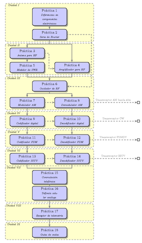
Listado de pr'acticas

Edit and compile if you like:
% Schema of Labs on a class
% Author: Cristo J. Alanis
\documentclass[11pt]{article}
\usepackage{tikz}
\usepackage[active,tightpage]{preview}
\PreviewEnvironment{tikzpicture}
\setlength\PreviewBorder{5pt}%
\usetikzlibrary{shadows,arrows}
% Define the layers to draw the diagram
\pgfdeclarelayer{background}
\pgfdeclarelayer{foreground}
\pgfsetlayers{background,main,foreground}

% Define block styles
\tikzstyle{materia}=[draw, fill=blue!20, text width=6.0em, text centered,
  minimum height=1.5em,drop shadow]
\tikzstyle{practica} = [materia, text width=8em, minimum width=10em,
  minimum height=3em, rounded corners, drop shadow]
\tikzstyle{texto} = [above, text width=6em, text centered]
\tikzstyle{linepart} = [draw, thick, color=black!50, -latex', dashed]
\tikzstyle{line} = [draw, thick, color=black!50, -latex']
\tikzstyle{ur}=[draw, text centered, minimum height=0.01em]

% Define distances for bordering
\newcommand{\blockdist}{1.3}
\newcommand{\edgedist}{1.5}

\newcommand{\practica}[2]{node (p#1) [practica]
  {Pr\'actica #1\\{\scriptsize\textit{#2}}}}

% Draw background
\newcommand{\background}[5]{%
  \begin{pgfonlayer}{background}
    % Left-top corner of the background rectangle
    \path (#1.west |- #2.north)+(-0.5,0.5) node (a1) {};
    % Right-bottom corner of the background rectanle
    \path (#3.east |- #4.south)+(+0.5,-0.25) node (a2) {};
    % Draw the background
    \path[fill=yellow!20,rounded corners, draw=black!50, dashed]
      (a1) rectangle (a2);
    \path (a1.east |- a1.south)+(0.8,-0.3) node (u1)[texto]
      {\scriptsize\textit{Unidad #5}};
  \end{pgfonlayer}}

\newcommand{\transreceptor}[3]{%
  \path [linepart] (#1.east) -- node [above]
    {\scriptsize Transreceptor #2} (#3);}

\begin{document}
\begin{tikzpicture}[scale=0.7,transform shape]

  % Draw diagram elements
  \path \practica {1}{Diferencias en componentes electr\'onicos};
  \path (p1.south)+(0.0,-1.0) \practica{2}{Serie de Fourier};
  \path (p2.south)+(-2.5,-1.5) \practica{3}{Antena para HF};
  \path (p3.south)+(0.0,-1.0) \practica{5}{Medidor de SWR};
  \path (p3.south)+(5.0,-1.0) \practica{4}{Amplificador para HF};

  \path (p4.south)+(-2.5,-1.5) \practica{6}{Oscilador de RF};
  \path (p6.south)+(-2.5,-1.25) \practica{7}{Modulador AM};
  \path (p6.south)+(2.5,-1.25) \practica{8}{Demodulador AM};
  \path (p8.east)+(+5.5,0) node (ur1)[ur] {};

  \path (p7.south)+(0.0,-1.5) \practica{9}{Codificador digital};
  \path (p8.south)+(0.0,-1.5) \practica{10}{Decodificador digital};
  \path (p10.east)+(+5.5,0) node (ur2)[ur] {};
  \path (p9.south)+(0.0,-1.5) \practica{11}{Codificador FDM};
  \path (p10.south)+(0.0,-1.5) \practica{12}{Decodificador FDM};
  \path (p12.east)+(+5.5,0) node (ur3)[ur] {};
  \path (p11.south)+(0.0,-1.5) \practica{13}{Codificador SSTV};
  \path (p12.south)+(0.0,-1.5) \practica{14}{Decodificador SSTV};
  \path (p14.east)+(+5.5,0) node (ur4)[ur] {};
  \path (p14.south)+(-2.5,-1.5) \practica{15}{Conmutaci\'on telef\'onica};
  \path (p15.south)+(0.0,-1.0) \practica{16}{Telfon\'ia celular an\'aloga};
  \path (p16.south)+(0.0,-1.5) \practica{17}{Receptor de  telemetr\'ia};
  \path (p17.south)+(0.0,-1.5) \practica{18}{Gu\'ias de ondas};

  % Draw arrows between elements
  \path [line] (p1.south) -- node [above] {} (p2);

  \path [line] (p2.south) -- +(0.0,-0.5) -- +(-2.5,-0.5)
    -- node [above, midway] {} (p3);
  \path [line] (p3.south) -- node [above] {} (p5) ;

  \path [line] (p2.south) -- +(0.0,-0.5) -- +(+2.5,-0.5)
    -- node [above, midway] {} (p4);
  \path [linepart] (p3.east) -- +(+0.5,-0.0) -- +(+0.5,-1.75)
    -- node [left, midway] {} (p4);
  \path [linepart] (p3.east) -- +(+0.5,-0.0) -- +(+0.5,-1.75)
    -- node [left, midway] {} (p4);

  \path [line] (p4.south) -- +(0.0,-0.5) -- +(-2.5,-0.5)
    -- node [above, midway] {} (p6);
  \path [line] (p5.south) -- +(0.0,-0.5) -- +(+2.5,-0.5)
    -- node [above, midway] {} (p6);
  \path [linepart] (p2.east) -- +(2.75,0.0) -- +(2.75,-5.85)
    -- node [right] {} (p6);
  \path [line] (p6.south) -- +(0.0,-0.25) -- +(-2.5,-0.25)
    -- node [above, midway] {} (p7);
  \path [line] (p6.south) -- +(0.0,-0.25) -- +(+2.5,-0.25)
    -- node [above, midway] {} (p8);
  \path [linepart] (p7.east) -- node [left] {} (p8);
  \transreceptor{p8}{AM banda 40m}{ur1}

  \path [line] (p7.south) -- node [above] {} (p9) ;
  \path [line] (p8.south) -- node [above] {} (p10) ;
  \path [linepart] (p9.east) -- node [left] {} (p10);
  \transreceptor{p10}{CW}{ur2}
  \path [line] (p9.south) -- node [above] {} (p11) ;
  \path [line] (p10.south) -- node [above] {} (p12) ;
  \path [linepart] (p11.east) -- node [left] {} (p12);
  \transreceptor{p12}{FDMDV}{ur3}

  \path [line] (p11.south) -- node [above] {} (p13) ;
  \path [line] (p12.south) -- node [above] {} (p14) ;
  \path [linepart] (p13.east) -- node [left] {} (p14);
  \transreceptor{p14}{SSTV}{ur4}

  \path [line] (p14.south) -- +(0.0,-0.5) -- +(-2.5,-0.5)
    -- node [above, midway] {} (p15);
  \path [line] (p13.south) -- +(0.0,-0.5) -- +(+2.5,-0.5)
    -- node [above, midway] {} (p15);
  \path [line] (p15.south) -- node [above] {} (p16) ;
  \path [line] (p16.south) -- node [above] {} (p17) ;
  \path [line] (p17.south) -- node [above] {} (p18) ;

  \background{p3}{p1}{p4}{p2}{I}
  \background{p3}{p3}{p4}{p5}{II}
  \background{p3}{p6}{p4}{p7}{III}
  \background{p3}{p9}{p4}{p10}{IV}
  \background{p3}{p11}{p4}{p12}{V}
  \background{p3}{p13}{p4}{p14}{VI}
  \background{p3}{p15}{p4}{p16}{VII}
  \background{p3}{p17}{p4}{p17}{VIII}
  \background{p3}{p18}{p4}{p18}{IX}
\end{tikzpicture}
\end{document}
Click to download: labs-schema.tex • labs-schema.pdf
Open in Overleaf: labs-schema.tex


