


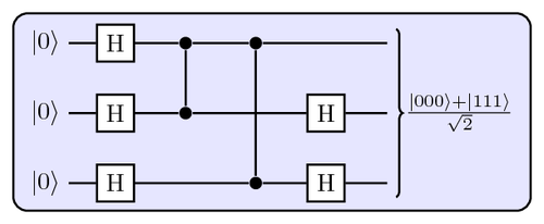
This code produces an image of a "quantum circuit" that produces a Greenberger-Horne-Zeilinger (GHZ) state, which is important for tests of nonlocality. This is an example of how simple it is to draw quantum circuits using TikZ.
Edit and compile if you like:
% Quantum circuit
% Author:

% This code produces an image of a `quantum circuit' that produces
% a Greenberger-Horne-Zeilinger (GHZ) state, which is important
% for tests of nonlocality. This is an example of how simple it is
% to draw quantum circuits using TikZ.

\documentclass[10pt]{article}

\usepackage[hang,small,bf]{caption}    % fancy captions
\usepackage{tikz}

\usetikzlibrary{backgrounds,fit,decorations.pathreplacing}                  % TikZ libraries
\newcommand{\ket}[1]{\ensuremath{\left|#1\right\rangle}} % Dirac Kets

\usepackage[active,tightpage]{preview}
\PreviewEnvironment{tikzpicture}
\setlength\PreviewBorder{5pt}%


\begin{document}
\begin{figure}
  \centerline{
    \begin{tikzpicture}[thick]
    %
    % `operator' will only be used by Hadamard (H) gates here.
    % `phase' is used for controlled phase gates (dots).
    % `surround' is used for the background box.
    \tikzstyle{operator} = [draw,fill=white,minimum size=1.5em]
    \tikzstyle{phase} = [fill,shape=circle,minimum size=5pt,inner sep=0pt]
    \tikzstyle{surround} = [fill=blue!10,thick,draw=black,rounded corners=2mm]
    %
    % Qubits
    \node at (0,0) (q1) {\ket{0}};
    \node at (0,-1) (q2) {\ket{0}};
    \node at (0,-2) (q3) {\ket{0}};
    %
    % Column 1
    \node[operator] (op11) at (1,0) {H} edge [-] (q1);
    \node[operator] (op21) at (1,-1) {H} edge [-] (q2);
    \node[operator] (op31) at (1,-2) {H} edge [-] (q3);
    %
    % Column 3
    \node[phase] (phase11) at (2,0) {} edge [-] (op11);
    \node[phase] (phase12) at (2,-1) {} edge [-] (op21);
    \draw[-] (phase11) -- (phase12);
    %
    % Column 4
    \node[phase] (phase21) at (3,0) {} edge [-] (phase11);
    \node[phase] (phase23) at (3,-2) {} edge [-] (op31);
    \draw[-] (phase21) -- (phase23);
    %
    % Column 5
    \node[operator] (op24) at (4,-1) {H} edge [-] (phase12);
    \node[operator] (op34) at (4,-2) {H} edge [-] (phase23);
    %
    % Column 6
    \node (end1) at (5,0) {} edge [-] (phase21);
    \node (end2) at (5,-1) {} edge [-] (op24);
    \node (end3) at (5,-2) {} edge [-] (op34);
    %
    % Bracket
    \draw[decorate,decoration={brace},thick] (5,0.2) to
	node[midway,right] (bracket) {$\frac{\ket{000}+\ket{111}}{\sqrt{2}}$}
	(5,-2.2);
    %
    % Background Box
    \begin{pgfonlayer}{background}
    \node[surround] (background) [fit = (q1) (op31) (bracket)] {};
    \end{pgfonlayer}
    %
    \end{tikzpicture}
  }
  \caption{
    A quantum circuit for producing a GHZ state using
    Hadamard gates and controlled phase gates.
  }
\end{figure}
\end{document}}
Click to download: quantum-circuit.tex • quantum-circuit.pdf
Open in Overleaf: quantum-circuit.tex