")


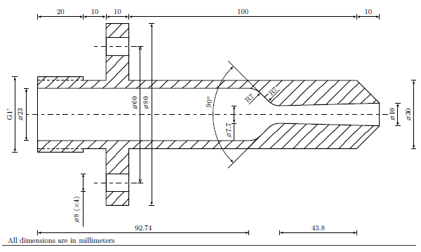
This is a cold air supersonic nozzle I used for my master thesis. The super sonic flow is reachable with a total upstream pressure of 7.7bar.
Edit and compile if you like:
% Supersonic technical drawing
% Author: Michele Muccioli
\documentclass{standalone}
\usepackage{tikz}
\usetikzlibrary{calc,patterns,arrows,shapes.arrows,intersections}
\usetikzlibrary{decorations}
\usepackage{wasysym}
\usepackage{siunitx}
%%%%%%%%%%%%%%%%%%%%%%%%%%%%%%
% SECTION PATTERN DEFINITION %
%%%%%%%%%%%%%%%%%%%%%%%%%%%%%%
\newlength\thickness
\pgfdeclarepatternformonly[\thickness]{section}
{\pgfpointorigin}
{\pgfpoint{1cm}{1cm}}
{\pgfpoint{1cm}{1cm}}
{
\pgfsetlinewidth{\thickness}
\pgfpathmoveto{\pgfpoint{0cm}{0cm}}
\pgfpathlineto{\pgfpoint{1cm}{1cm}}
\pgfpathclose
\pgfsetlinewidth{\thickness}
\pgfpathmoveto{\pgfpoint{0cm}{.5cm}}
\pgfpathlineto{\pgfpoint{.5cm}{1cm}}
\pgfpathclose
\pgfsetlinewidth{\thickness}
\pgfpathmoveto{\pgfpoint{.5cm}{0cm}}
\pgfpathlineto{\pgfpoint{1cm}{.5cm}}
\pgfusepath{stroke}
}

\tikzset{
thickness/.store in = \thickness,
thickness           = 0.5pt
}
%%%%%%%%%%%%%%%%%%%%%%%%%
% DIMENSION DECORATIONS %
%%%%%%%%%%%%%%%%%%%%%%%%%
\makeatletter
%-> New if
\newif\if@dim@connection

%-> New TeX dimensions
\newdimen\dim@x
\newdimen\dim@y
\newdimen\dim@sep
\newdimen\dim@overline
\newdimen\dim@overlineI
\newdimen\dim@overlineII
\newdimen\dim@text@translation

% x=, y=
%\newif\iftikz@isdimension
%\def\tikz@checkunit#1{%
%  \pgfmathparse{#1}%
%  \let\iftikz@isdimension=\ifpgfmathunitsdeclared%
%}
%\tikz@checkunit{1}
%\iftikz@isdimension
%true
%\else
%false
%\fi

% output scale
%  \pgf@pt@x=\pgf@x%
%  \pgf@pt@y=\pgf@y%
%  \let\pgf@pt@aa=\pgf@tempaa%
%  \let\pgf@pt@ba=\pgf@tempba%
%  \let\pgf@pt@ab=\pgf@tempab%
%  \let\pgf@pt@bb=\pgf@tempbb%
%  \def\pgf@trans@idtest{#1,#2,#3,#4}%
%  \ifx\pgf@trans@idtest\pgf@trans@idtext%
%  \else%
%    \pgf@pt@identityfalse%->\ifpgf@pt@identity
%  \fi%

%-> Horizontal dimension
\pgfdeclaredecoration{Hdim}{final}{%
\state{final}{%
% Setting needed dimensions from pgfkeys values.
\tikz@checkunit{\pgfkeysvalueof{/pgf/decoration/distance}}
\iftikz@isdimension
	\pgfmathsetlength{\dim@sep}{\pgfkeysvalueof{/pgf/decoration/distance}}
\else
	\pgfmathsetlength{\dim@sep}{\pgfkeysvalueof{/pgf/decoration/distance}*\pgf@yy}
\fi
\pgfmathsetlength{\dim@x}{\pgfdecoratedpathlength*cos(\pgfdecoratedangle)}
\pgfmathsetlength{\dim@y}{\pgfdecoratedpathlength*sin(\pgfdecoratedangle)}
\pgfmathsetlength{\dim@overline}{\pgfkeysvalueof{/pgf/decoration/overline}}
\pgfmathsetlength{\dim@text@translation}{\pgfkeysvalueof{/pgf/decoration/text translation}}
% Setting text to write from pgfkeys value.
\def\dim@text{\pgfkeysvalueof{/pgf/decoration/text}}
% The overline verse (where it points. Positive or negative) depends
% on dimension sep and angle of the segment to dimension.
\ifdim0pt<\dim@sep
	% Case with positive dimension sep.
	% Normal behaviour.
	\pgfmathsetlength{\dim@overlineI}{\dim@overline}
	\pgfmathsetlength{\dim@overlineII}{\dim@overline}
\else
	% Case with negative dimension sep.
	% The value of dimension overline I is different from
	% dimension overline II and it depends on the
	% quadrant where the the segment is.
	\pgfmathparse{abs(\dim@sep) Vertical dimension (NOT UTILISED IN THE FOLLOWING DRAWING)
\pgfdeclaredecoration{Vdim}{final}{%
\state{final}{%
% Setting needed dimensions from pgfkeys values.
\tikz@checkunit{\pgfkeysvalueof{/pgf/decoration/distance}}
\iftikz@isdimension
	\pgfmathsetlength{\dim@sep}{\pgfkeysvalueof{/pgf/decoration/distance}}
\else
	\pgfmathsetlength{\dim@sep}{\pgfkeysvalueof{/pgf/decoration/distance}*\pgf@yy}
\fi
\pgfmathsetlength{\dim@x}{\pgfdecoratedpathlength*cos(\pgfdecoratedangle)}
\pgfmathsetlength{\dim@y}{\pgfdecoratedpathlength*sin(\pgfdecoratedangle)}
\pgfmathsetlength{\dim@overline}{\pgfkeysvalueof{/pgf/decoration/overline}}
\pgfmathsetlength{\dim@text@translation}{\pgfkeysvalueof{/pgf/decoration/text translation}}
% Setting text to write from pgfkeys value.
\def\dim@text{\pgfkeysvalueof{/pgf/decoration/text}}
% The overline verse (where it points. Positive or negative) depends
% on dimension sep and angle of the segment to dimension.
\ifdim0pt<\dim@sep
	% Case with positive dimension sep.
	% Normal behaviour.
	\pgfmathsetlength{\dim@overlineI}{\dim@overline}
	\pgfmathsetlength{\dim@overlineII}{\dim@overline}
\else
	% Case with negative dimension sep.
	% The value of dimension overline I is different from
	% dimension overline II and it depends on the
	% quadrant where the the segment is.
	\pgfmathparse{abs(\dim@sep)\pgfdecoratedangle
		% Third quadrant
		% Node drawing. It can be translate along the path with
		% text translation option.
		{
 		\pgftransformshift{\pgfpoint{\dim@sep}{\dim@y/2-\dim@text@translation}}
		% In this case, the node must e rotated.
		\pgftransformrotate{-90}
		% Capturing the TikZ picture font size
		\dim@text@font
		\pgfnode{rectangle}{south}{\dim@text}{\dim@text@nodename}{\pgfusepath{discard}}
		}
		% Drawing the connection segments.
		\pgfpathmoveto{\pgfpoint{\dim@sep+\dim@overlineI}{0pt}}
		% Check if the first connection line must be drawn.
		\if@dim@connection
			\pgfpathlineto{\pgfpoint{0pt}{0pt}}
		\else
			\pgfpathlineto{\pgfpoint{\dim@sep-\dim@overlineI}{0pt}}
		\fi
		\pgfpathmoveto{\pgfpoint{\dim@sep+\dim@overlineII}{\dim@y}}
		% Check if the second connection line must be drawn.
		\if@dim@connection
			\pgfpathlineto{\pgfpoint{\dim@x}{\dim@y}}
		\else
			\pgfpathlineto{\pgfpoint{\dim@sep-\dim@overlineII}{\dim@y}}
		\fi
		% Draw an extra line if node text lies outside of the
		% dimension.
		\pgfmathparse{abs(.5\dim@y)\pgfdecoratedangle
		% First quadrant
		% Node drawing. It can be translate along the path with
		% text translation option.
		{
 		\pgftransformshift{\pgfpoint{\dim@x+\dim@sep}{\dim@y/2-\dim@text@translation}}
		% In this case, the node must e rotated.
		\pgftransformrotate{-90}
		% Capturing the TikZ picture font size
		\dim@text@font
		\pgfnode{rectangle}{south}{\dim@text}{\dim@text@nodename}{\pgfusepath{discard}}
		}
		% Drawing the connection segments.
		\pgfpathmoveto{\pgfpoint{\dim@x+\dim@sep+\dim@overlineI}{0pt}}
		% Check if the first dimension connection must be drawn.
		\if@dim@connection
			\pgfpathlineto{\pgfpoint{0pt}{0pt}}
		\else
			\pgfpathlineto{\pgfpoint{\dim@x+\dim@sep-\dim@overlineI}{0pt}}
		\fi
		\pgfpathmoveto{\pgfpoint{\dim@x+\dim@sep+\dim@overlineII}{\dim@y}}
		% Check if the second dimension connection must be drawn.
		\if@dim@connection
			\pgfpathlineto{\pgfpoint{\dim@x}{\dim@y}}
		\else
			\pgfpathlineto{\pgfpoint{\dim@x+\dim@sep-\dim@overlineII}{\dim@y}}
		\fi
		% Draw an extra line if node text lies outside of the
		% dimension.
		\pgfmathparse{abs(.5\dim@y) Along the dimension
\pgfdeclaredecoration{dim}{final}{
\state{final}{%
% Check if the dimension inserted has unit
\tikz@checkunit{\pgfkeysvalueof{/pgf/decoration/distance}}
\iftikz@isdimension
	\pgfmathsetlength{\dim@sep}{\pgfkeysvalueof{/pgf/decoration/distance}}
\else
	\pgfmathsetlength{\dim@sep}{\pgfkeysvalueof{/pgf/decoration/distance}*\pgf@yy}
\fi
% Overline value if function of the sep sign.
\ifdim0pt>\dim@sep
	\pgfmathsetlength{\dim@overline}{-\pgfkeysvalueof{/pgf/decoration/overline}}
\else
	\pgfmathsetlength{\dim@overline}{\pgfkeysvalueof{/pgf/decoration/overline}}
\fi
\pgfmathsetlength{\dim@text@translation}{\pgfkeysvalueof{/pgf/decoration/text translation}}
% Setting the text to be inserted into the dimension node.
\def\dim@text{\pgfkeysvalueof{/pgf/decoration/text}}
{
\pgftransformshift{\pgfpoint{\pgfdecoratedpathlength/2+\dim@text@translation}{\dim@sep}}
% Capturing the TikZ picture font size
\dim@text@font
\pgfnode{rectangle}{south}{\dim@text}{\dim@text@nodename}{\pgfusepath{discard}}
}
\pgfpathmoveto{\pgfpoint{0pt}{\dim@sep+\dim@overline}}
% Check if the first connection line mus b drawn
\if@dim@connection
	\pgfpathlineto{\pgfpoint{0pt}{0pt}}
\else
	\pgfpathlineto{\pgfpoint{0pt}{\dim@sep-\dim@overline}}
\fi
\pgfpathmoveto{\pgfpoint{(\pgfdecoratedpathlength}{\dim@sep+\dim@overline}}
% Check if the first connection line mus b drawn
\if@dim@connection
	\pgfpathlineto{\pgfpoint{\pgfdecoratedpathlength}{0pt}}
\else
	\pgfpathlineto{\pgfpoint{(\pgfdecoratedpathlength}{\dim@sep-\dim@overline}}
\fi
% Draw an extra line if node text lies outside of the
% dimension.
\pgfmathparse{abs(.5*\pgfdecoratedpathlength) Initial values
\pgfkeys{/pgf/decoration/.cd,
         distance/.initial         = 10pt,
         overline/.initial         = 1mm,
         text/.initial             = {},
         text translation/.initial = 0pt,
         text node name/.store in  = \dim@text@nodename,
         text node name            = dim_text,
         >/.store in               = \dim@arrow@type,
         >                         = latex,
         connection/.is if         = @dim@connection,
         connection                = false,
         font/.store in            = \dim@text@font,
         font                      = \tikz@textfont,
}
\makeatother

%%%%%%%%%%%%%%%%%%%%%%%%%%%%%%%%%%%%%%%%%%
% COMMANDS TO CALL DIMENSION DECORATIONS %
%%%%%%%%%%%%%%%%%%%%%%%%%%%%%%%%%%%%%%%%%%
\newcommand\Hdimension[1][]{\path[decorate,decoration={Hdim,#1}]}
\newcommand\Vdimension[1][]{\path[decorate,decoration={Vdim,#1}]}
\newcommand\dimension[1][]{\path[decorate,decoration={dim,#1}]}

\begin{document}
\begin{tikzpicture}[x         = 1mm,
                    y         = 1mm,
                    >         = latex,
                    line join = round,
                    font      = \small]

%%%%%%%%%%%%%%%%%%
% NOZZLE DRAWING %
%%%%%%%%%%%%%%%%%%
%-> Origin definition
\coordinate (o) at (0,0);

%-> Nozzle
% Symmetric characteristic is used in a
% foreach command where the cycle is made
% for upper part (up) with positive sign (+)
% and lower part (down) with negative sign (-)
\foreach \pos/\sign in {up/+,down/-}{

%%-> Points definitions
\coordinate (A\pos)        at ($(o)+(0,\sign11.5)$);
\coordinate (B\pos)        at ($(A\pos)+(0,\sign5.075)$);
\coordinate (C\pos)        at ($(B\pos)+(20,0)$);
\coordinate (D\pos)        at ($(C\pos)+(0,-\sign1.575)$);
\coordinate (E\pos)        at ($(D\pos)+(10,0)$);
\coordinate (F\pos)        at ($(E\pos)+(0,\sign11)$);
\coordinate (G\pos)        at ($(F\pos)+(0,\sign8)$);
\coordinate (H\pos)        at ($(G\pos)+(0,\sign6)$);
\coordinate (I\pos)        at ($(H\pos)+(10,0)$);
\coordinate (L\pos)        at (G\pos-|I\pos);
\coordinate (M\pos)        at (F\pos-|I\pos);
\coordinate (N\pos)        at (E\pos-|I\pos);
\coordinate (O\pos)        at ($(N\pos)+(100,0)$);
\coordinate (P\pos)        at ($(O\pos)+(10,-\sign10)$);
\coordinate (throat_\pos)  at ($(P\pos)-(43.8,\sign1.15)$);
\coordinate (IN_\pos)      at ($(A\pos)+(92.74,0)$);
\coordinate (center1_\pos) at ($(o)+(92.74,\sign4.5)$);
\coordinate (center2_\pos) at ($(throat_\pos)+(0,\sign7)$);

%%-> Draw nozzle main body
\draw[fill,
      pattern    = section,
      line width = 1.1pt]
\ifnum\sign1>0
        (center1_\pos)++(45:7)arc(45:90:7)--
\else
        (center1_\pos)++(-45:7)arc(315:270:7)--
\fi
(A\pos)--
(B\pos)--
(C\pos)--
(D\pos)--
(E\pos)--
(F\pos)--
(G\pos)--
(H\pos)--
(I\pos)--
(L\pos)--
(M\pos)--
(N\pos)--
(O\pos)--
(P\pos)--
(throat_\pos)
\ifnum\sign1>0
      arc(270:225:7)
\else
     arc(90:135:7)
\fi
--cycle;

%%-> Draw holes on the flange
\draw[fill       = white,
      line width = 1.1pt] (G\pos)rectangle(M\pos);

%%-> Draw symmetric axis on flange holes
\draw[dash pattern = on 3pt off 5pt on 6pt off 5pt,
      line width   = 1pt] ($(F\pos)!.5!(G\pos)-(5,0)$)--
                          ($(L\pos)!.5!(M\pos)+(5,0)$);

%%-> screw drawing
\draw[dashed] (D\pos)--(D\pos-|A\pos);
}

%%-> Nozzle input and output closure
\draw[line width = 1.1pt](Adown)--(Aup)
                         (Pdown)--(Pup);

%%-> Nozzle symmetry line
\draw[dash pattern = on 3pt off 5pt on 6pt off 5pt,
      line width   = 1pt] ($(Adown)!.5!(Aup)-(5,0)$)--($(Pdown)!.5!(Pup)+(5,0)$);

%%%%%%%%%%%%%%
% DIMENSIONS %
%%%%%%%%%%%%%%
% Macro to see the dimension
% inserted. For debug.
\newif\ifdimension
\dimensionfalse
%\dimensiontrue % if true, you will see the dimension number (%x) on the draw
\newcount\Ndim=0
\def\SeeDim#1{\ifdimension\global\advance\Ndim by 1 \the\Ndim\else#1\fi}
%-> 1
\Hdimension[text      = \SeeDim{10},
            distance  = 3]  (Hup) --  (Iup);

%-> 2
\Hdimension[text     = \SeeDim{10},
            distance = 3] (Cup)--(Hup);

%-> 3
\Hdimension[text     = \SeeDim{20},
            distance = 26.425] (Bup)--(Cup);

%-> 4
\Hdimension[text     = \SeeDim{100},
            distance = 3] (Iup)--(Oup);

%-> 5
\Hdimension[text     = \SeeDim{10},
            distance = 28] (Oup)--(Pup);

%-> 6
\dimension[text     = \SeeDim{\diameter30},
           distance = -25] (Odown)--(Oup);

%-> 7
\Hdimension[text     = \SeeDim{43.8},
            distance = -48.15] (throat_down)--(Odown);

%-> 8
\Hdimension[text     = \SeeDim{92.74},
            distance = -40.5] (IN_down)--(Bdown);

%-> 9
\dimension[text             = \SeeDim{\diameter7.7},
           text translation = -7mm,
           distance         = 20] (throat_down)--(throat_up);

%-> 10
\dimension[text     = \SeeDim{\diameter10},
           distance = -8] (Pdown)--(Pup);

%-> 11 (by hand)
\draw[->] (center1_up)--++(45:7)node[sloped,
                                     above     = .4mm,
                                     pos       = .3,
                                     inner sep = 0.5pt]{\SeeDim{R7}};

%-> 12 (by hand)
\draw[->] (center2_up)--++(225:7)node[above     = .4mm,
                                      pos       = .4,
                                      inner sep = 0.5pt,
                                      rotate    = 45,
                                      fill      = white]{\SeeDim{R7}};

%-> 13 (by hand)
\coordinate (raccordo_up)   at ($(center1_up)+(45:7)$);
\coordinate (raccordo_down) at ($(center1_down)+(-45:7)$);
\draw (raccordo_up)--++(135:20);
\draw (raccordo_down)--++(225:20);
\path[name path=C1](raccordo_up)--++(-45:20);
\path[name path=C2](raccordo_down)--++(45:20);
\path[name intersections={of=C1 and C2}];
\coordinate (C90) at (intersection-1);
\draw[<->] ($(C90)+(135:30)$)arc[start angle = 135,
                                 delta angle = 90,
                                 radius      = 30];
\def\angle{35}
\node[rotate = \angle+45,
      anchor = south] at ($(C90)+(135+\angle:30)$){\SeeDim{\ang{90}}};

%-> 14
\dimension[text             = \SeeDim{\diameter60},
           distance         = -5,
           >                = angle 45,
           text translation = .5cm] ($(Ldown)!.5!(Mdown)$)--($(Lup)!.5!(Mup)$);

%-> 15
\dimension[text             = \SeeDim{\diameter80},
           distance         = -10,
           text translation = .5cm] (Idown)--(Iup);

%-> 16
\dimension[text             = \SeeDim{\diameter8 ($\times$4)},
           distance         = 10,
           text translation = -12mm] (Gdown)--(Fdown);

%-> 17
\dimension[text     = \SeeDim{G1'},
           distance = 10] (Bdown)--(Bup);

%-> 18
\dimension[text     = \SeeDim{\diameter23},
           distance = 5] (Adown)--(Aup);

% Dimensions scale
\node[anchor = north west] at (current bounding box.south west)
{All dimensions are in millimeters};
\end{tikzpicture}
\end{document}
Click to download: supersonic-nozzle.tex • supersonic-nozzle.pdf
Open in Overleaf: supersonic-nozzle.tex