


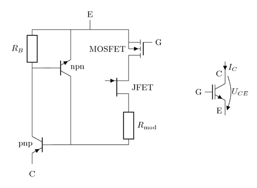
Equivalent circuit of the non-punch through (NPT) type insulated gate bipolar transistor (IGBT). Adapted from the schematic in the book by Jouko Niiranen (2007).
Symbol with voltage and current of the NPT-type IGBT.
Edit and compile if you like:
% Insulated gate bipolar transistor (IGBT).
% Author: Erno Pentzin (2013)
\documentclass{article}
\usepackage{tikz}
\usepackage[active,tightpage]{preview}
\PreviewEnvironment{tikzpicture}
\setlength\PreviewBorder{10pt}%
\usepackage[europeanresistors,americaninductors]{circuitikz}
\usepackage{amsmath}
\begin{document}

\begin{circuitikz}
% Equivalent circuit:
\begin{scope}[scale=0.8]
\draw (0,2) to[Tpnp,n=pnp] (0,0)
      (pnp.E) node[below=2mm] {C} % Collector (of the (whole) IGBT)
      (pnp.B) node[left=7mm] {pnp}

      (0,7) to[R,l_=$R_B$] (0,5) -- (pnp.C) % body region spreading resistance

      (0,7) -- (5,7)

      to[Tnigfete,n=mosfet] (5,5) % MOSFET
      to[Tnjfet,n=jfet,mirror] (5,3) % JFET
      to[R,l=$R_{\text{mod}}$] (5,1) % drift region resistance (modulated)
      -- (pnp.B)

      (mosfet.G) node[anchor=west] {G} % Gate
      (mosfet.B) node[anchor=east] {MOSFET}
      (jfet) node[anchor=west] {JFET}

      (2,7) -- (2,6) to[Tnpn,n=npn,mirror] (2,4) -- (2,1)
      (npn.B) -- (0,5)
      (npn.B) node[right=7mm] {npn}

      (3,7.5) to[short,n=IGBTE] (3,7) % Emitter
      (IGBTE) node[above=2mm] {E};
\end{scope}

% Symbol with voltage and current:
\draw (8,3) node[nigbt] (igbt) {}
      (igbt.C) node[anchor=east] {C} % Collector
      (igbt.B) node[anchor=east] {G} % Gate
      (igbt.E) node[anchor=east] {E} % Emitter

      (igbt.C) to [short, i<_=$I_C$] +(0,+5mm) %current
      (igbt.C) to [open, v^>=$U_{CE}$] (igbt.E) -- +(0,-2mm); %voltage
\end{circuitikz}
\end{document}
Click to download: insulated-gate-bipolar-transistor.tex • insulated-gate-bipolar-transistor.pdf
Open in Overleaf: insulated-gate-bipolar-transistor.tex