


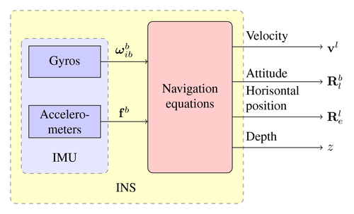
A block diagram of an inertial measurement unit (IMU) combined with navigation equations to form an inertial navigation system (INS). A handful of useful tricks have been used to align blocks and arrows nicely. Hard coding coordinates has been avoided as much as possible.
Edit and compile if you like:
\documentclass{article}

\usepackage{tikz}
\usetikzlibrary{shapes,arrows}
\usepackage{amsmath,bm,times}


\newcommand{\mx}[1]{\mathbf{\bm{#1}}} % Matrix command
\newcommand{\vc}[1]{\mathbf{\bm{#1}}} % Vector command

\begin{document}
\pagestyle{empty}

% We need layers to draw the block diagram
\pgfdeclarelayer{background}
\pgfdeclarelayer{foreground}
\pgfsetlayers{background,main,foreground}

% Define a few styles and constants
\tikzstyle{sensor}=[draw, fill=blue!20, text width=5em,
    text centered, minimum height=2.5em]
\tikzstyle{ann} = [above, text width=5em]
\tikzstyle{naveqs} = [sensor, text width=6em, fill=red!20,
    minimum height=12em, rounded corners]
\def\blockdist{2.3}
\def\edgedist{2.5}

\begin{tikzpicture}
    \node (naveq) [naveqs] {Navigation equations};
    % Note the use of \path instead of \node at ... below.
    \path (naveq.140)+(-\blockdist,0) node (gyros) [sensor] {Gyros};
    \path (naveq.-150)+(-\blockdist,0) node (accel) [sensor] {Accelero-meters};

    % Unfortunately we cant use the convenient \path (fromnode) -- (tonode)
    % syntax here. This is because TikZ draws the path from the node centers
    % and clip the path at the node boundaries. We want horizontal lines, but
    % the sensor and naveq blocks aren't aligned horizontally. Instead we use
    % the line intersection syntax |- to calculate the correct coordinate
    \path [draw, ->] (gyros) -- node [above] {$\vc{\omega}_{ib}^b$}
        (naveq.west |- gyros) ;
    % We could simply have written (gyros) .. (naveq.140). However, it's
    % best to avoid hard coding coordinates
    \path [draw, ->] (accel) -- node [above] {$\vc{f}^b$}
        (naveq.west |- accel);
    \node (IMU) [below of=accel] {IMU};
    \path (naveq.south west)+(-0.6,-0.4) node (INS) {INS};
    \draw [->] (naveq.50) -- node [ann] {Velocity } + (\edgedist,0)
        node[right] {$\vc{v}^l$};
    \draw [->] (naveq.20) -- node [ann] {Attitude} + (\edgedist,0)
        node[right] { $\mx{R}_l^b$};
    \draw [->] (naveq.-25) -- node [ann] {Horisontal position} + (\edgedist,0)
        node [right] {$\mx{R}_e^l$};
    \draw [->] (naveq.-50) -- node [ann] {Depth} + (\edgedist,0)
        node[right] {$z$};

    % Now it's time to draw the colored IMU and INS rectangles.
    % To draw them behind the blocks we use pgf layers. This way we
    % can use the above block coordinates to place the backgrounds
    \begin{pgfonlayer}{background}
        % Compute a few helper coordinates
        \path (gyros.west |- naveq.north)+(-0.5,0.3) node (a) {};
        \path (INS.south -| naveq.east)+(+0.3,-0.2) node (b) {};
        \path[fill=yellow!20,rounded corners, draw=black!50, dashed]
            (a) rectangle (b);
        \path (gyros.north west)+(-0.2,0.2) node (a) {};
        \path (IMU.south -| gyros.east)+(+0.2,-0.2) node (b) {};
        \path[fill=blue!10,rounded corners, draw=black!50, dashed]
            (a) rectangle (b);
    \end{pgfonlayer}
\end{tikzpicture}


\end{document}
Click to download: inertial-navigation-system.tex • inertial-navigation-system.pdf
Open in Overleaf: inertial-navigation-system.tex