


A circuit from a paper about measuring HBT RF linearity and intermodulation distortion.
It uses very few absolute coordinates, so everything aligns nicely and is easily modifiable.
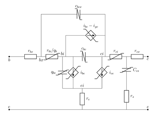
Edit and compile if you like:
% Circuit example
% Author: Magnus Rentsch Ersdal
\documentclass[border=10pt,12pt]{standalone}
\usepackage[siunitx]{circuitikz} % Loading circuitikz with siunitx option
\begin{document}
\begin{circuitikz}[american currents,european resistors]
  \draw %horizontal main components
    (0,0) node[coordinate](origin){} to[short,*-] ++(1,0)
    to[R,l=$r_{bx}$,name=Rbx]    ++(2,0) node [coordinate] (bx) {$b_x$}
    to[R,l=$r_{bi}/q_b$,name=Rbi] +(2,0) node [coordinate] (bi) {$b_i$}
    to[C,l=$c_{bc}$,name=Cbc]     +(4,0) node [coordinate] (ci) {$c_i$}
    to[R,l=$r_{ci}$,name=Rci]     +(2,0) node [coordinate] (rc)      {}
    to[R,l=$r_{cx}$,-*,name=Rcx]  +(2,0) node [coordinate] (c)       {}
  ;
  \draw %current sources
    ($(bi)+(0.3,0)$) |- ++(1,2) node [coordinate] (t2) {}
    to[cI=$i_{bc}-i_{gc}$,name=c1] (t2-|ci)
    ($(ci)+(-0.3,0)$) to[cI=$i_{ce}$,name=c3] ++(0,-3) node [coordinate] (t3) {}
    ($(bi)+(1,0)$) node[coordinate](t4){} to[cI=$i_{be}$,name=c2] (t4|-t3)
  ;
  \draw %qbe and cbcx
    (bx) |- ++(1,4) node[coordinate](t1) {}
    to[C,l=$c_{bcx}$,name=Cbcx] (t1-|ci)
    (bi) to[C,l_=$q_{be}$,name=qbe] (bi|-t3)
    (t1-|ci)--(ci)
  ;
  \draw
    ($(bi|-t3)!0.5!(t3)$)            node [coordinate] (t5) {}
    to[R,l=$r_{e}$,name=Re] ++(0,-2) node [coordinate] (t6) {}
    (bi|-t3)--(t3)
  ;
  \draw
    ($(rc)!0.5!(rc|-t6)$) node[coordinate] (t7) {}
    (rc) to[C,l=$C_{cs}$,name=Ccs] (t7)
    (t7) to[R,l=$r_{s}$,name=Rs] (rc|-t6)
    (origin|-t6) to[short,*-*] (t6-|c)
  ;
  %labels
  \draw (origin|-t6) node [anchor=south]       {$e$}
        (t6-|c)      node [anchor=south]       {$e$}
        (c)          node [anchor=north]       {$c$}
        (origin)     node [anchor=north]       {$b$}
        (bx)         node [anchor=north]      {$bx$}
        (bi)         node [anchor=south]      {$bi$}
        (ci)         node [anchor=south east] {$ci$}
        (t5)         node [anchor=south]      {$ei$};

  %nonlinear lines (messy)
  \begin{scope}[thick]
    \def\doff{0.1}
    %horizontal Resistors
    \draw ($(Rbi.sw)-(0.2,\doff)$) --  ($(Rbi.sw)+(0,-\doff)$)
      --  ($(Rbi.ne)+(0,\doff)$)   -- ($(Rbi.ne)+(0.2,\doff)$)
          ($(Rci.sw)-(0.2,\doff)$) --  ($(Rci.sw)+(0,-\doff)$)
      --  ($(Rci.ne)+(0,\doff)$)   -- ($(Rci.ne)+(0.2,\doff)$);

    %horizontal Capacitors
    \draw ($(Cbc.nw)+(-0.2,\doff)$)  --     ($(Cbc.nw)+(0,\doff)$)
      --  ($(Cbc.se)-(0,\doff)$)     --  ($(Cbc.se)-(-0.2,\doff)$)
          ($(Cbcx.nw)+(-0.2,\doff)$) --    ($(Cbcx.nw)+(0,\doff)$)
      --  ($(Cbcx.se)-(0,\doff)$)    -- ($(Cbcx.se)-(-0.2,\doff)$)
          ($(c1.nw)+(-0.2,\doff)$)   --      ($(c1.nw)+(0,\doff)$)
      --  ($(c1.se)-(0,\doff)$)      --   ($(c1.se)-(-0.2,\doff)$);

    %vertical curr
    \draw ($(c3.nw)+(0.2,\doff)$) --   ($(c3.nw)+(0,\doff)$)
      --  ($(c3.se)-(0,\doff)$)   -- ($(c3.se)-(0.2,\doff)$)
          ($(c2.nw)+(0.2,\doff)$) --   ($(c2.nw)+(0,\doff)$)
      --  ($(c2.se)-(0,\doff)$)   -- ($(c2.se)-(0.2,\doff)$);

    % Vertical c
    \draw ($(qbe.nw)+(0.2,\doff)$) --   ($(qbe.nw)+(0,\doff)$)
      --  ($(qbe.se)-(0,\doff)$)   -- ($(qbe.se)-(0.2,\doff)$)
          ($(Ccs.nw)+(0.2,\doff)$) --   ($(Ccs.nw)+(0,\doff)$)
      -- ($(Ccs.se)-(0,\doff)$)    -- ($(Ccs.se)-(0.2,\doff)$);
  \end{scope}
\end{circuitikz}
\end{document}
Click to download: circuit.tex • circuit.pdf
Open in Overleaf: circuit.tex