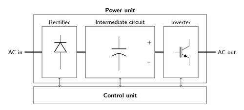
Generalized diagram of different components inside an AC drive with voltage intermediate circuit

Edit and compile if you like:
% Generalized diagram of different components inside an AC drive
% with voltage intermediate circuit
% Author: Erno Pentzin (2013)
\documentclass{article}
\usepackage{tikz}
\usepackage[active,tightpage]{preview}
\PreviewEnvironment{tikzpicture}
\setlength\PreviewBorder{10pt}%
\usepackage[europeanresistors,americaninductors]{circuitikz}
\usetikzlibrary{chains}
\renewcommand*{\familydefault}{\sfdefault}
\begin{document}

\begin{tikzpicture}[
	start chain=going right,
	box/.style={
		on chain,join,draw,
		minimum height=3cm,
		text centered,
		minimum width=2cm,
	},
	every join/.style={ultra thick},
	node distance=5mm
]

\node [on chain] {AC in}; % Chain starts here

\node [box,xshift=5mm,label=above:Rectifier] (rec) {
	\begin{circuitikz}
		\draw (0,0) to[Do] (0,2);
	\end{circuitikz}
};

\node [on chain,join,draw,
	text width=1cm,
	minimum width=4cm,
	minimum height=1.6cm,
	label=above:Intermediate circuit,
] (ic) {
	\begin{circuitikz}[american voltages]
		\draw (0,0) to[pC,v>=$ $] (0,2);
	\end{circuitikz}
};

\node [box,label=above:Inverter] (inv) {
	\begin{circuitikz}
		\draw (0,0) node[nigbt] {};
	\end{circuitikz}
};

\node [on chain,join,xshift=5mm]{AC out};
% Chain ends here

% CU box
\node [
	rectangle,draw,
	below=5mm of ic,
	minimum width=10cm,
	minimum height=1cm,
] (cu) {\textbf{Control unit}};

% PU box
\node [
	rectangle,draw,
	above=2mm of cu,
	minimum width=10cm,
	minimum height=4cm,
	label=\textbf{Power unit},
] (pu) {};

% Connections between CU and PU
\draw[<->] (rec.south) -- ++(0,-5mm);
\draw[<->] (cu.north) to (ic.south);
\draw[<->] (inv.south) -- ++(0,-5mm);

\end{tikzpicture}

\end{document}
Click to download: ac-drive-components.tex • ac-drive-components.pdf
Open in Overleaf: ac-drive-components.tex

