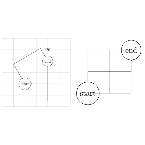
TikZ provides a convenient way of connecting two nodes using the to path operation (see chapter 13.13 in the manual). A handful of to-paths are available in the to path library, but you can also easily create your own.
Users familiar with Metapost and PSTricks may have noticed that TikZ does not directly provides a node connection operation similar to ncbar. In this entry I will create a TikZ versions of ncbar using to-paths.
This example defines a custom to-path called myncbar. Two options can be used to adjust the bar:
- angle
- The direction the connection is leaving the start node (default value is 0).
- arm
- The length from the start node to the right angle turn (default value is 1cm).
Here are a few examples:

\begin{tikzpicture}
    \draw[black!20] (-2,-2) grid (4,4);
    \node[draw,circle] at (0,0) (start) {start};
    \node[draw,circle] at (2,2) (end) {end};
    \draw (start) to[myncbar,arm=2cm,angle=120] node[auto] {120} (end);
    \draw[red,->] (end) to[myncbar] (start);
    \draw[blue,->] (start) to[myncbar,angle=-90,arm=1.5] (end);
\end{tikzpicture}
\end{document}
Note. This is a simplified version of the ncbar command available in PSTricks and Metaobj. There is only one arm option and if the arm is too short you will get a step-like path:
\begin{tikzpicture}
    \draw[black!20] (0,0) grid (2,2);
    \node[draw,circle] at (0,0) (start) {start};
    \node[draw,circle] at (2,2) (end) {end};
    \draw[->] (start) to[myncbar,angle=90,arm=1] (end);
\end{tikzpicture}

The code for the to-path is relatively straightforward. Note the use of the new coordinate calculation syntax ($...$) introduced in PGF 2.00. This syntax allows you to do some very useful calculations like for instance projections. I have also used the new let operation to initialize some coordinates that I need in order to draw the path. See chapter 13.14 in the manual for details.

Edit and compile if you like:
% Metapost style ncbar node connection
% Requires PGF 2.00 or later
\documentclass{article}

\usepackage{tikz}

% The calc library is needed for the ($...$) node calculation syntax.
\usetikzlibrary{calc}


\begin{document}

% Define the arm and angle options
\def\myarm{1cm}
\def\myangle{0}
\tikzset{
  arm/.default=1cm,
  arm/.code={\def\myarm{#1}}, % store value in \myarm
  angle/.default=0,
  angle/.code={\def\myangle{#1}} % store value in \myangle
}

% Define the myncbar to path
\tikzset{
    myncbar/.style = {to path={
        % We need to calculate a couple of coordinates to help us draw
        % the path.
        let
            % Same as (\tikztotarget)++(\myangle:\myarm)
            \p1=($(\tikztotarget)+(\myangle:\myarm)$)
        in
            -- ++(\myangle:\myarm) coordinate (tmp)
            % Find the projection of the (tmp) coordinate
            % on the line from the target to p1
            -- ($(\tikztotarget)!(tmp)!(\p1)$)
            -- (\tikztotarget)\tikztonodes
    }}
}
% Instead of the let operation we could probably have used the
% 'execute at begin to' option or the \pgfextra operation

\begin{tikzpicture}
    \draw[black!20] (-2,-2) grid (4,4);
    \node[draw,circle] at (0,0) (start) {start};
    \node[draw,circle] at (2,2) (end) {end};

    \draw (start) to[myncbar,arm=2cm,angle=120] node[auto] {120} (end);
    \draw[red,->] (end) to[myncbar] (start);
    \draw[blue,->] (start) to[myncbar,angle=-90,arm=1.5] (end);
\end{tikzpicture}

\begin{tikzpicture}
    \draw[black!20] (0,0) grid (2,2);
    \node[draw,circle] at (0,0) (start) {start};
    \node[draw,circle] at (2,2) (end) {end};

    \draw[->] (start) to[myncbar,angle=90,arm=1] (end);
\end{tikzpicture}

\end{document}
Click to download: myncbar.tex • myncbar.pdf
Open in Overleaf: myncbar.tex

